Background: Slots, Trays and all that Stuff
Accessories are installed on the Clinac by inserting them in one of the Slots below the collimator. Our Clinacs (2300C/D) have four slots:
- Slot 1: Internal Mount at 57.4 cm
- Slot 2: Accessory Mount at 65.4 cm
- Slot 4: Compensator Mount at 69.8 cm
- Slot 3: E-Insert at 95 cm
In ARIA, the slots can be found in the Administration application, under Radiation & Imaging Devices. A certain radiation device (= linac) has to be selected to see the tabs for slots.
The upper hard wedges are installed in slot 1. Slot 2 holds all the electron applicators. At the bottom of the applicators is slot 3, which accepts the electron cutouts. We never used slot 4, which can be used for the lower wedges or compensators.
Trays can also can be inserted into slots. The block tray is a typical tray. It goes into slot 2. Other trays are the electron ARC tray, the trays for total body irradiation (TBI X and TBI e-) or the FFDA tray, which is necessary for treating eMC calculated fields.
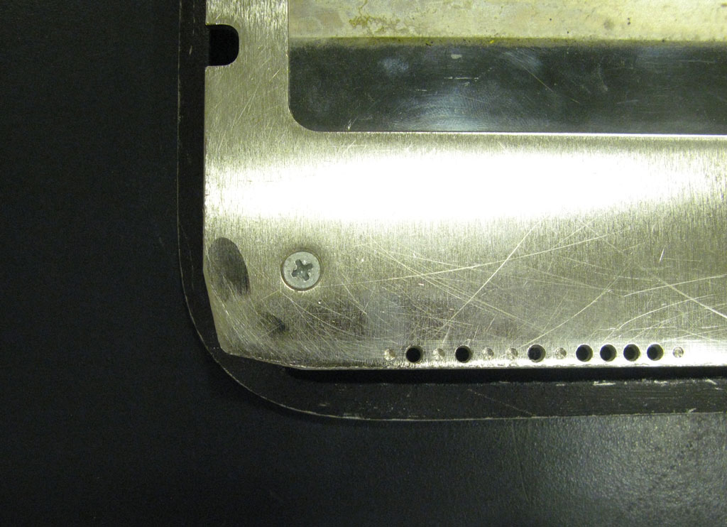
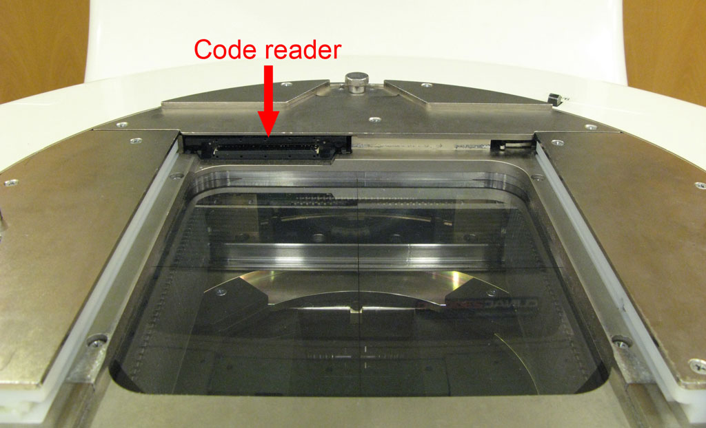
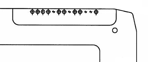
If a treatment field is planned for a certain accessory, the linac will check whether the accessory is in place. Otherwise the ACC interlock will prevent beam-on. For slot 1-accessories like hard wedges, the checking is done by reading a pattern of drilled holes in the right corner of the wedge (as seen in beams-eye view). The code pattern has 13 "bits", which are either drilled or not drilled (see typical hard wedge). The code is unique for the accessory. The Clinac reads the code and compares the installed accessory with the planned accessory.
The Add-On Materials are necessary for specifying dosimetric properties like transmission factors. They can be found under Clinical Data. "MLC" is the most important Add-On Material. Add-On Materials have a usage type (Block, Compensator, Tray, Wedge, MLC, ...) and assigned energies. Dosimetric tranmission factors are defined in Beam Configuration for each linac, energy, and material (e.g., the material MLC - usage type MLC - may have a transmission factor of 0.018 for 6 MV on linac 1). A material of usage type MLC (in contrast to a tray) has another dosimetric parameter: the Dosimetric Leaf Separation. That's why different usage types are necessary.
The "USER X" Solution
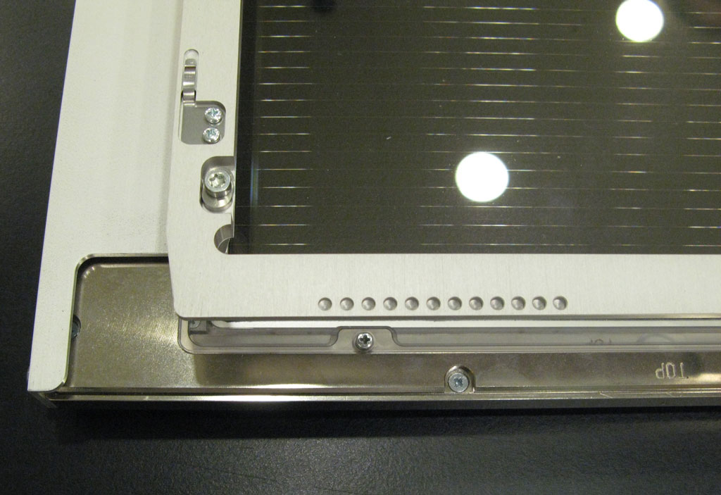
When we received DAVID for testing, it had no Clinac coding at all, so we could only use it in Service Mode. Twelve holes were "prepared", but not drilled through.
If DAVID shall be used with ARIA and a single tray factor is deemed sufficient for taking into account all dosimetric effects, it may be defined as a tray.
In our case, four steps were necessary:
- the raw DAVID frame had to be modified (= holes had to be drilled)
- in Administration, the linacs had to be configured for the USER X tray
- in Beam Configuration, a transmission factor had to be specified for 6 and 15 MV
- on the Clinac, the field size for the User X accessory had to be set to 40x40 cm
First we "copied" the USER X bit pattern to the DAVID frame, drilling nine holes with a 3 mm drill bit:
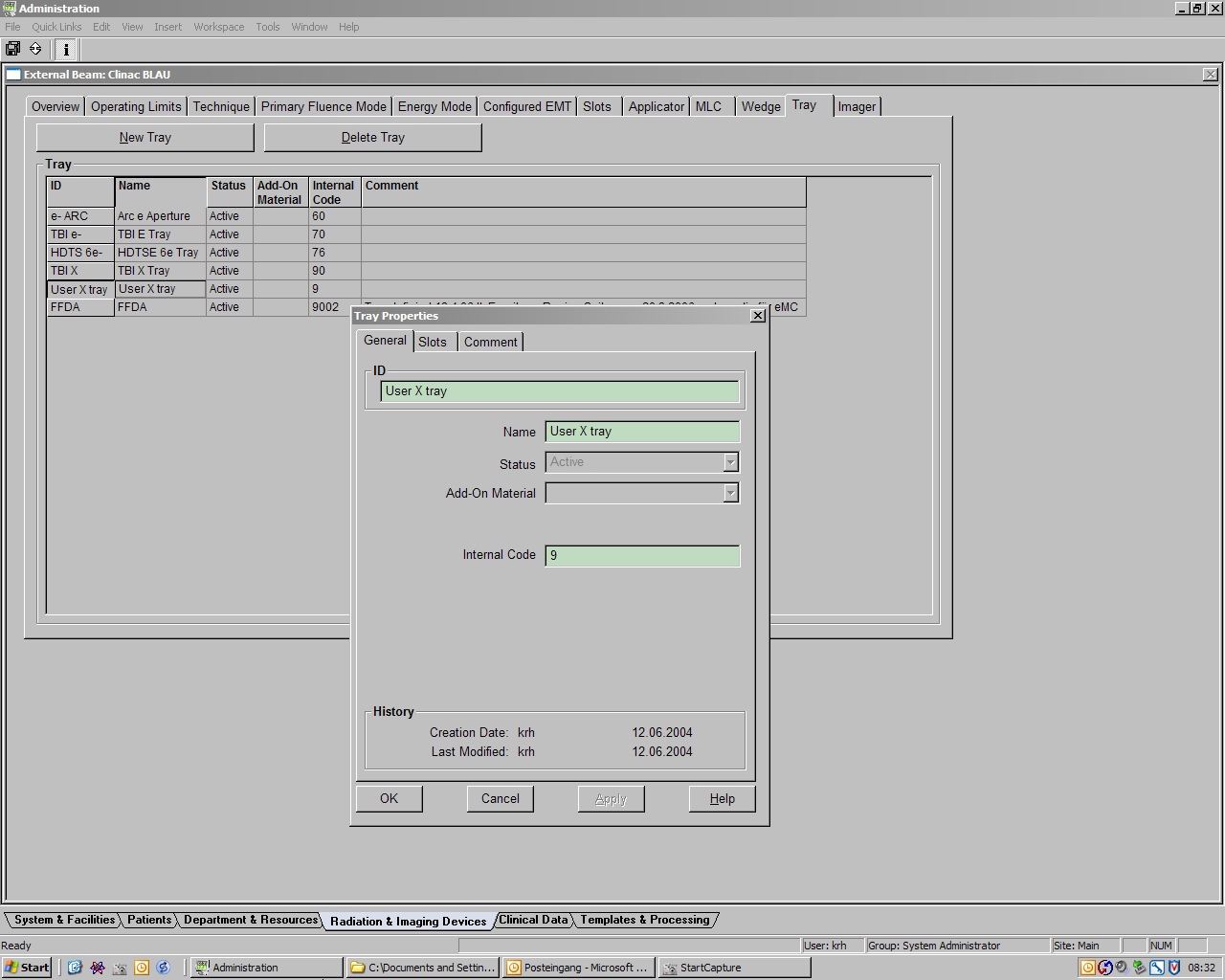
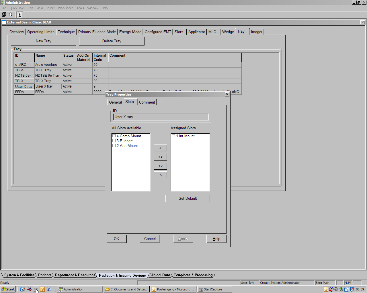
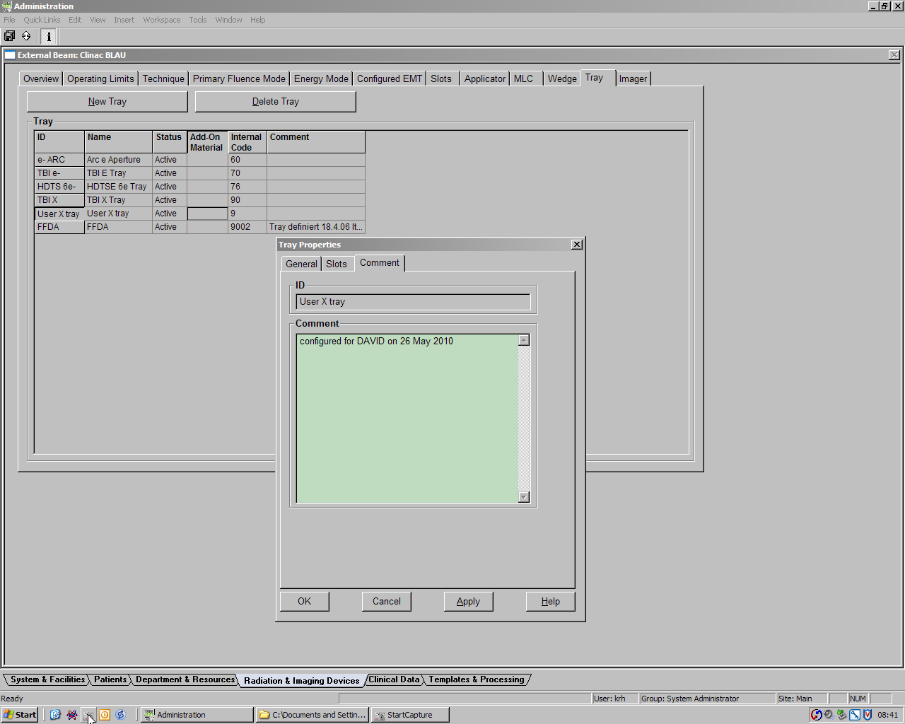
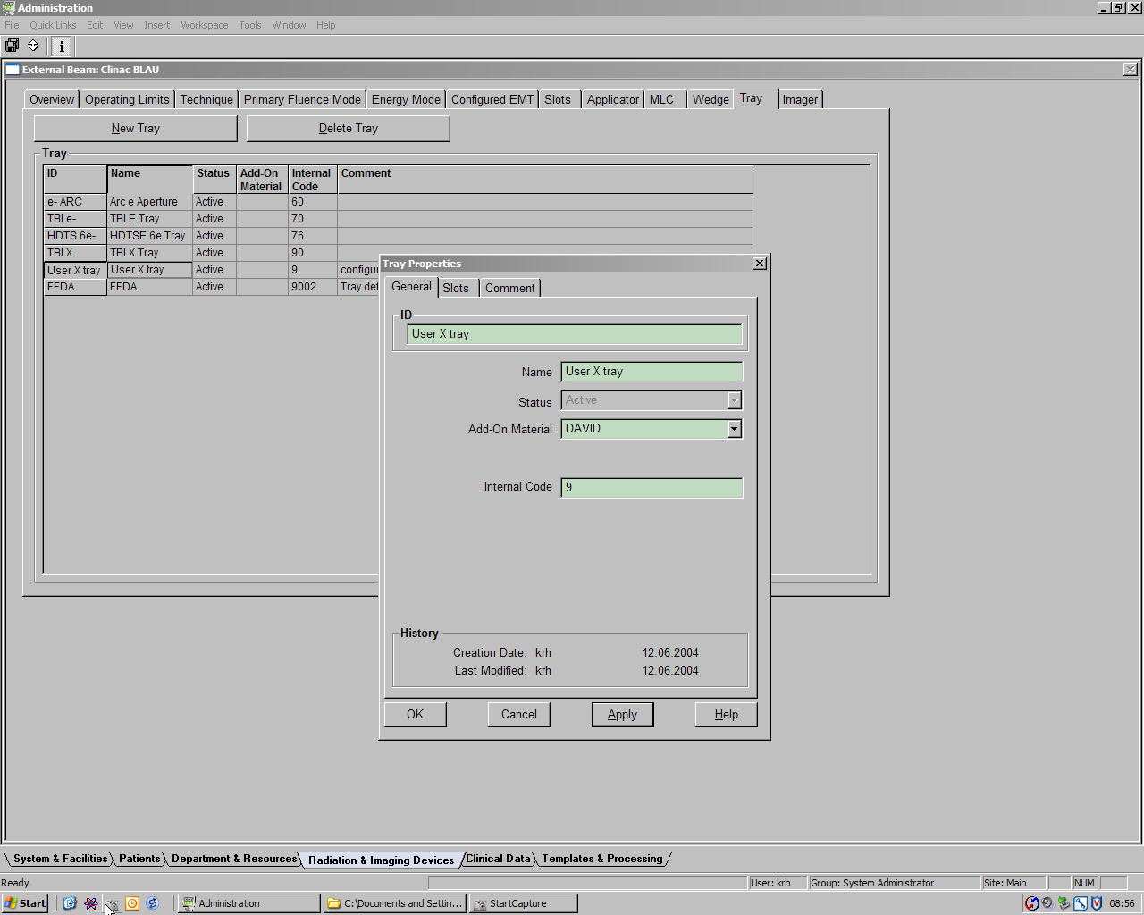
In Administration > Radiation & Imaging Devices > Tray, the User X tray was already defined, but no Add-On Material was assigned. The "Int Mount" is the assigned slot, we set it as default. It is always good to leave a comment.
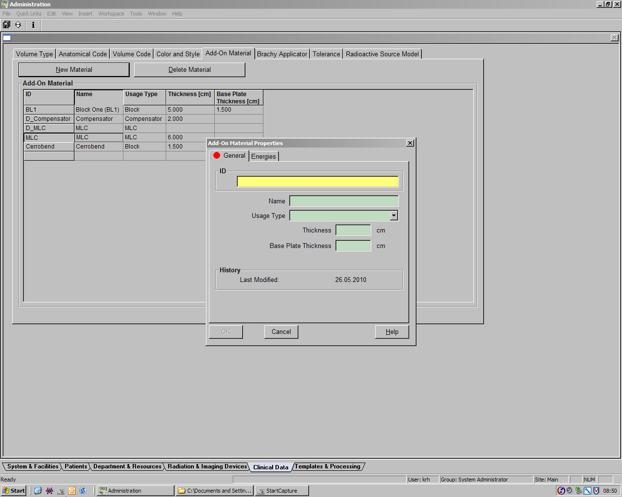
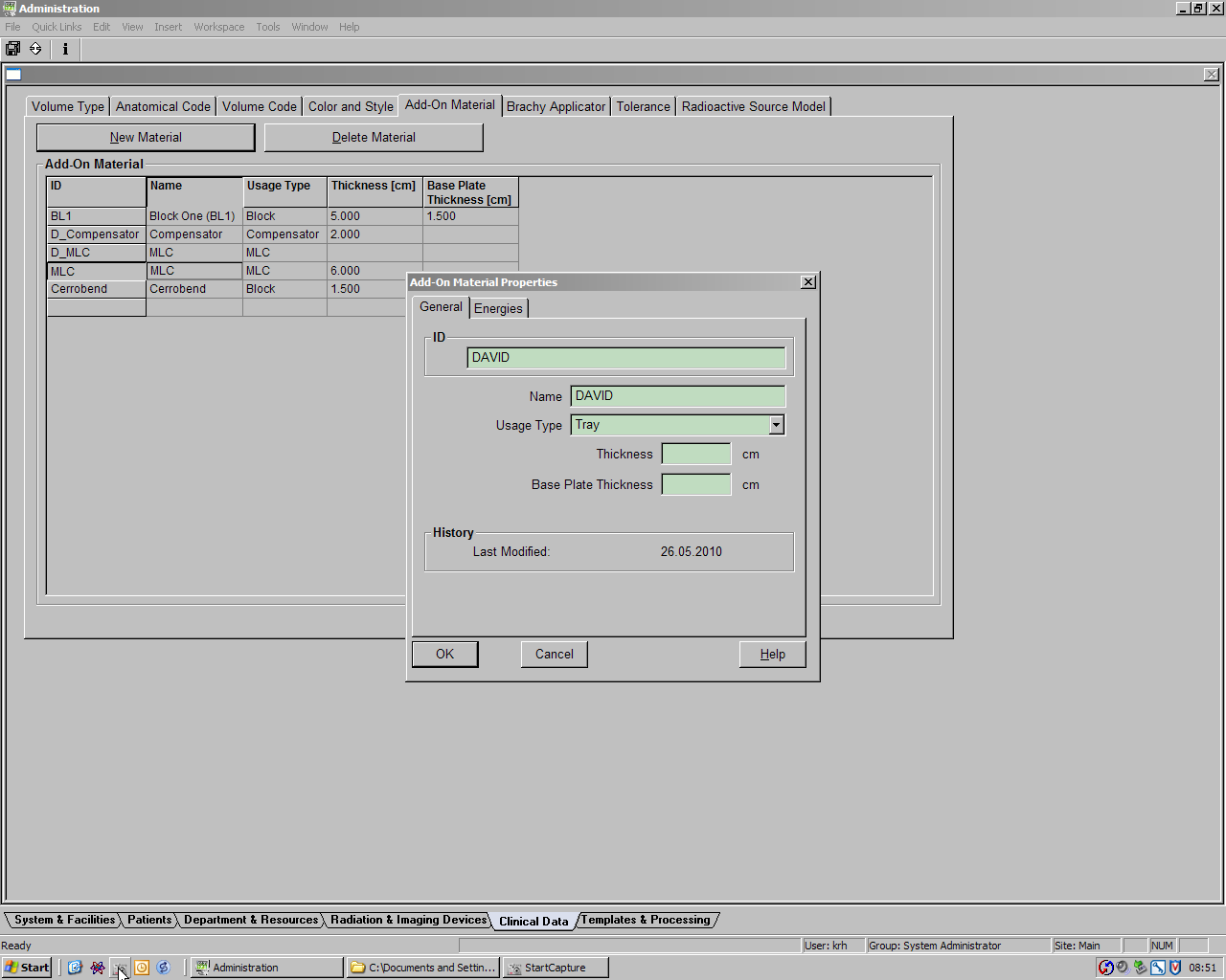
Under Clinical Data, we define a New Material and name it DAVID. We choose Tray as usage type. Thickness and Base Plate Thickness can be left empty. Now DAVID is a tray. Then we add the energies we want to use DAVID with.
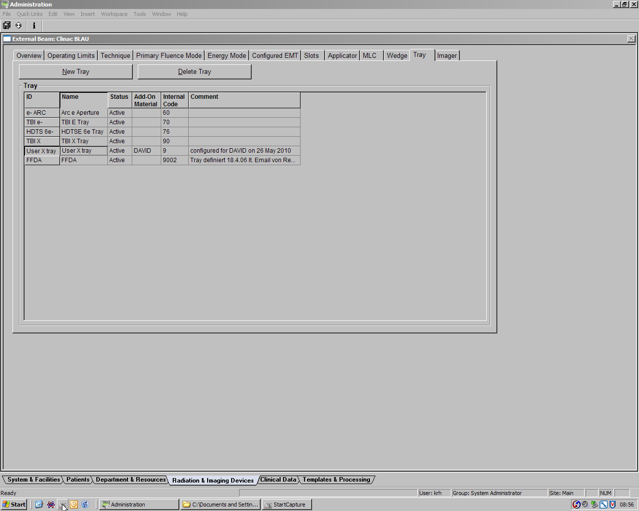
Back under Radiation & Imaging Devices > Tray, we can now select DAVID as Add-On Material for the User X tray. This is the finished Trays tab.
We save and switch to Eclipse/Beam Configuration, where we select a machine and one of the photon energies just added. From the Beam Data menu, we select Dosimetric Data. Now DAVID shows up with a transmission factor of 0.000000. Enter the transmission factor you have measured (see ours for comparison). The same has to be repeated for all linac/energy combinations. Now DAVID is configured for ARIA.
As a final configuration step, we had to change a field size limit on the Clinac console. For some unknown (probably security) reason, under Physics > Configuration > Field Sizes, the USER X was set to a maximum field size of 1x1 cm. This triggered a COLL interlock for typical field sizes, although the ACC was clear. We changed the limit to 40x40 cm.
Treatment Planning
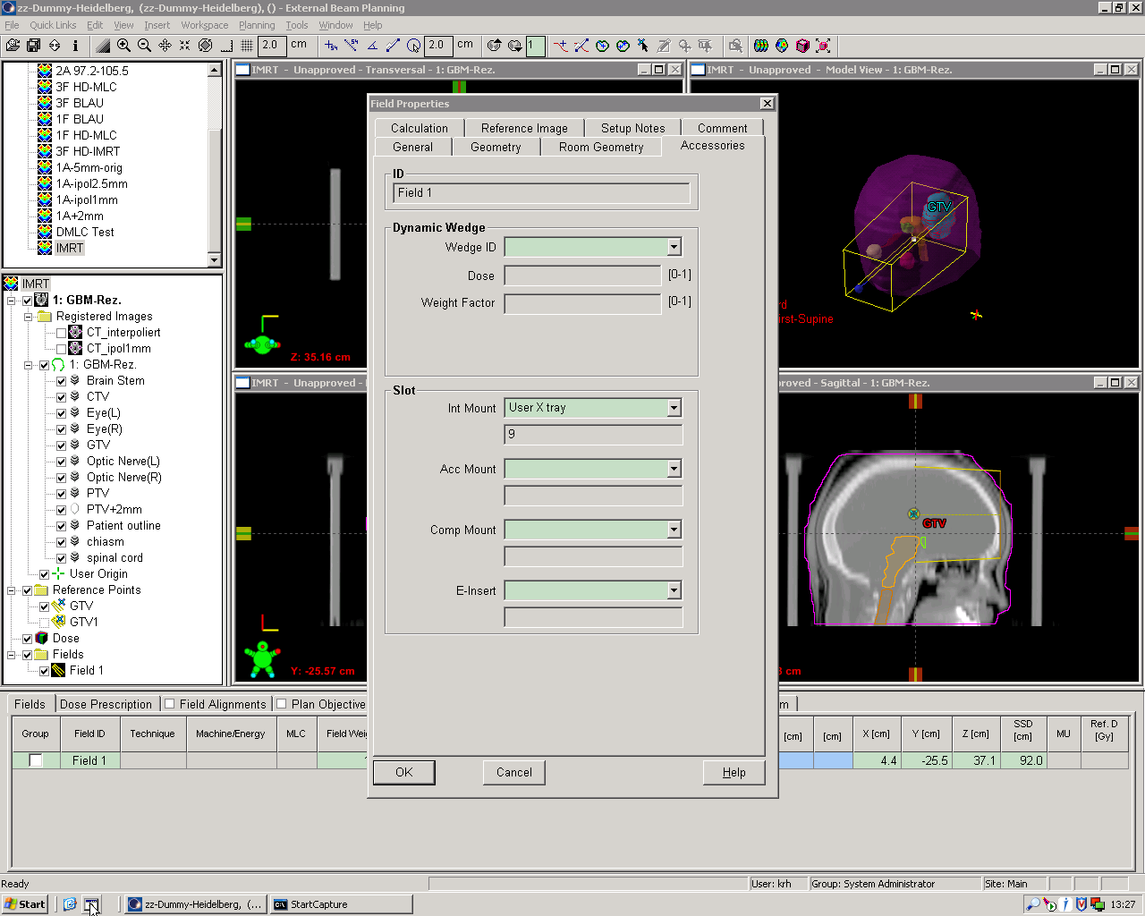
If "User X" is selected as accessory in Eclipse, the transmission factor will automatically be taken into account (and MU increased accordingly). This can be verified after dose calculation by checking the calculation notes.
When the user calculates dose, a warning that the tray is empty shows up. This is a little bit confusing but keep in mind that trays are typically used to put something on them.
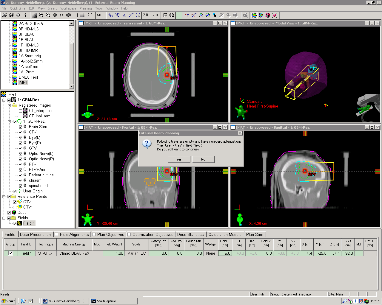
If a plan has multiple IMRT fields after beam angle optimization (where Eclipse will add and delete fields to find the optimal beam arrangement according to given constraints), the final field arrangement will have no trays, even if the starting field (with which the user initiated beam angle optimization) had one. This means that ater optimization finishes and before dose is calculated, the "User X" accessory has to be added manually to all fields. The warning can be used to check if all fields contain the necessary User X.
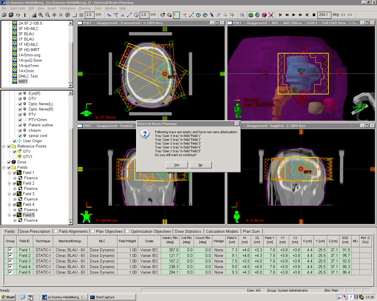