Before clinical measurements can be deconvoluted with David 2, the "LRF matrix" has to be measured for each photon energy of the linac.
Preparation in ARIA/Eclipse
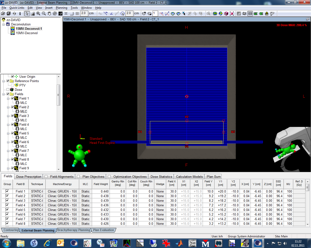
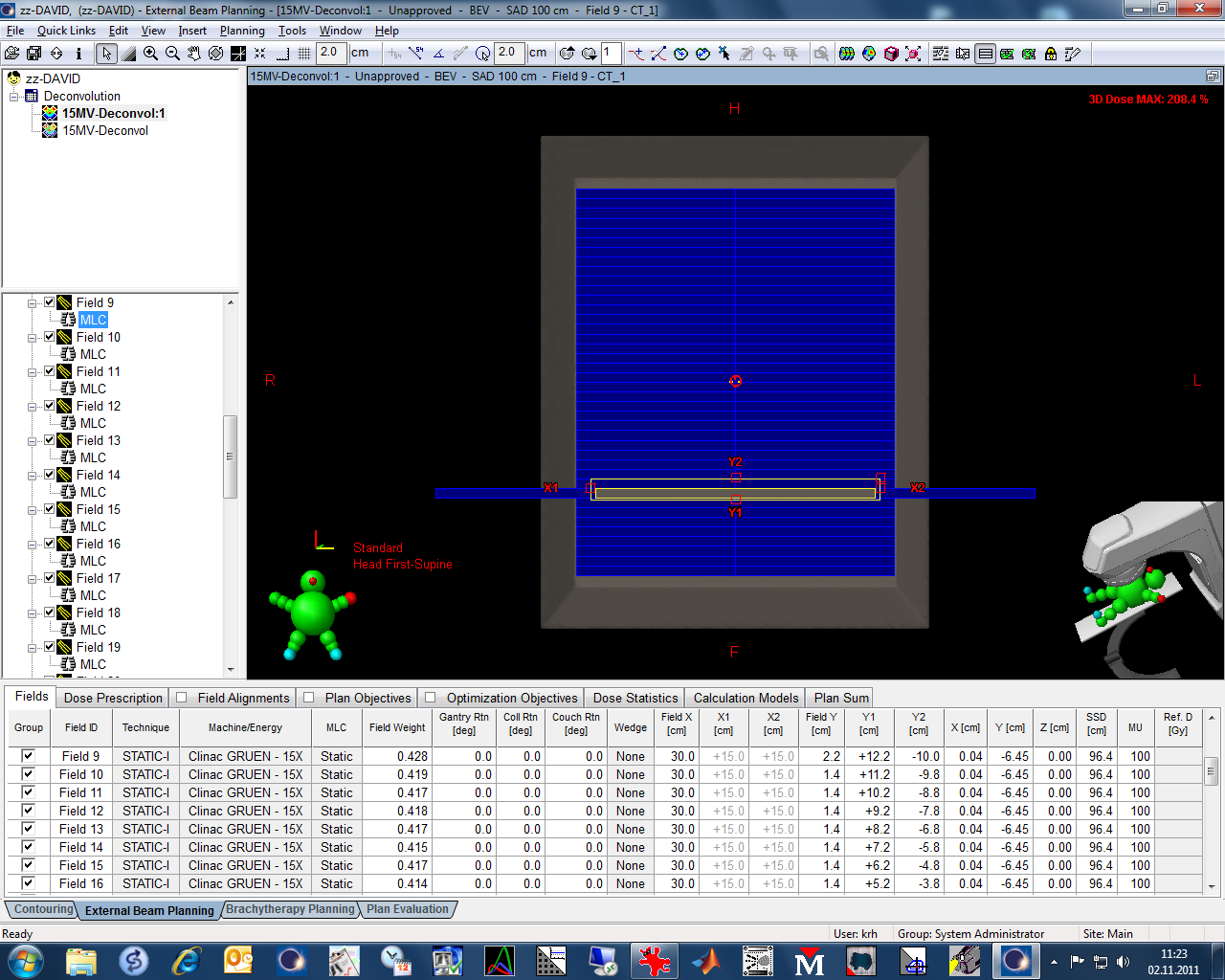
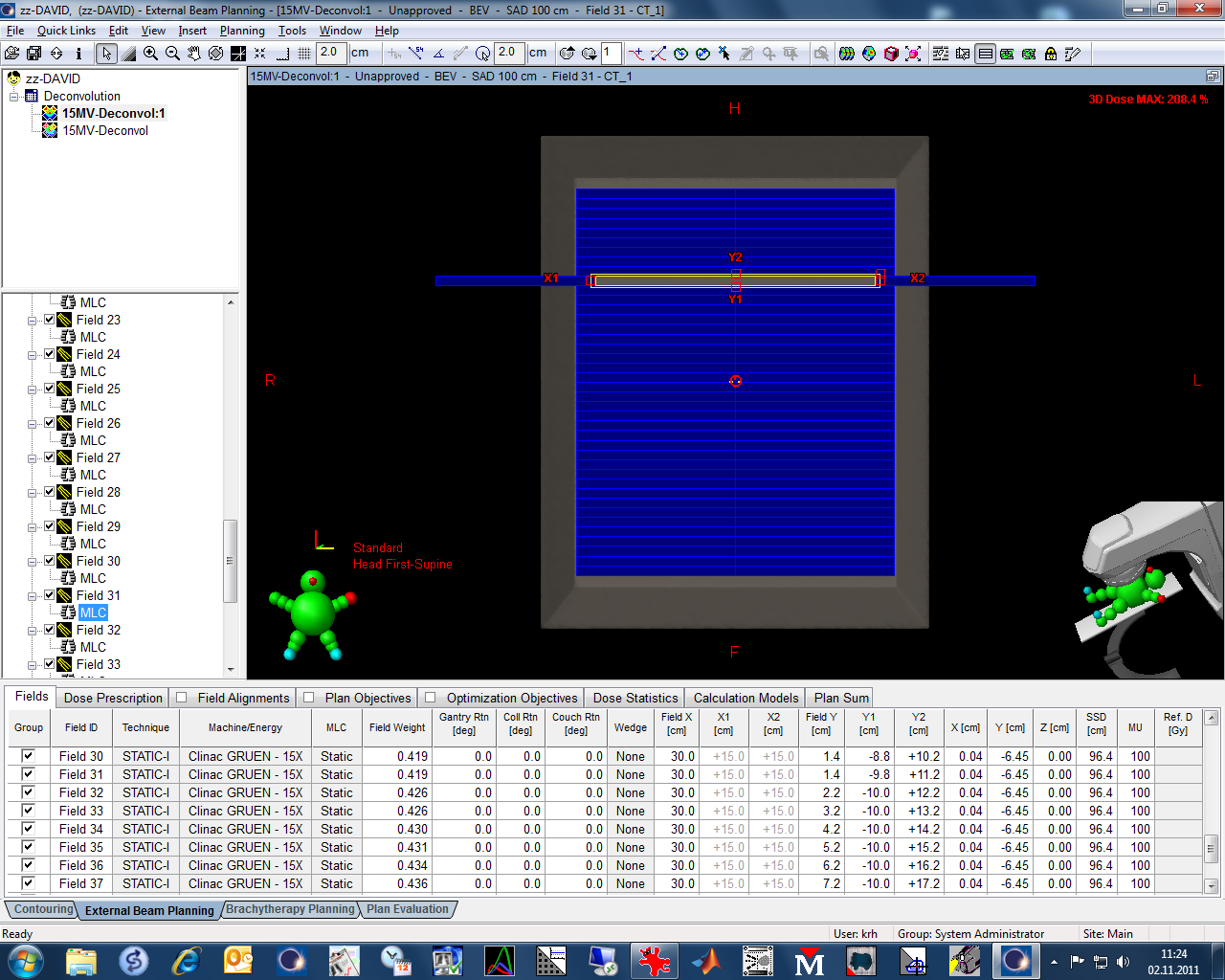
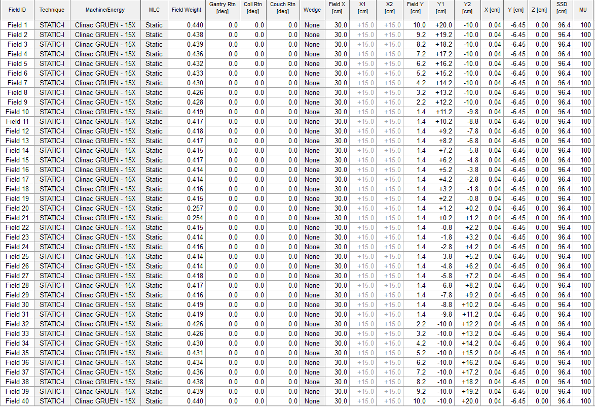
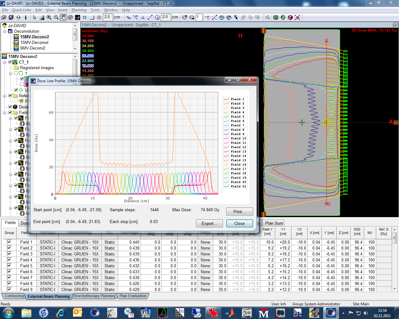
In Eclipse, we create a plan with 40 fields. In each field, exactly one leaf pair is open. The MLC-defined field size is 1 cm x 29 cm at isocenter. All leaf pairs except one are closed at midline. The jaw-defined field is 1.4 cm x 30 cm(1). Dose is calculated with a predefined 100 MU per field, so that the plan can be conveniently delivered via ARIA.
The following screenshot shows the field list for the 15 MV plan (MLCs are shown in the BEV of fields 2, 9, 10, 31 and 32):
(static image, click to enlarge)
Preparation in David Software
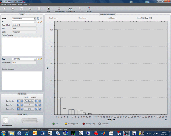
The LRF plan in David software only has a single beam, not 40. Beam interruptions between the ARIA fields are interpreted as segments, and David software expects exactly 40 segments if the device has 40 channels. Also, the ARIA field order is not arbitrary: David software expects that the LRF measurement starts by exposing channel 1 and ends with channel 40.
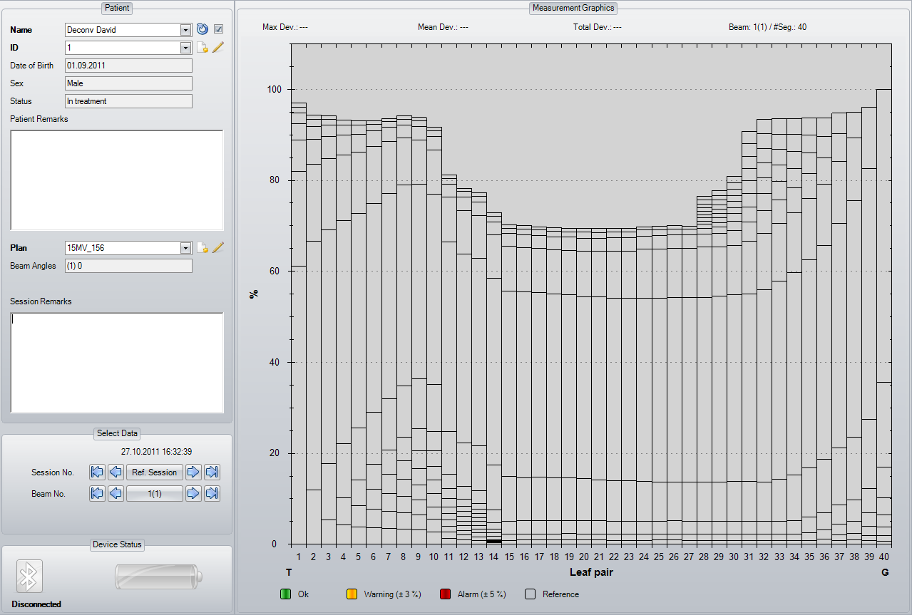
The resulting LRF matrix (see 2D-plot) is saved and applied during each successive clinical measurements, if the user chooses to use deconvolution.
Varian Peculiarities
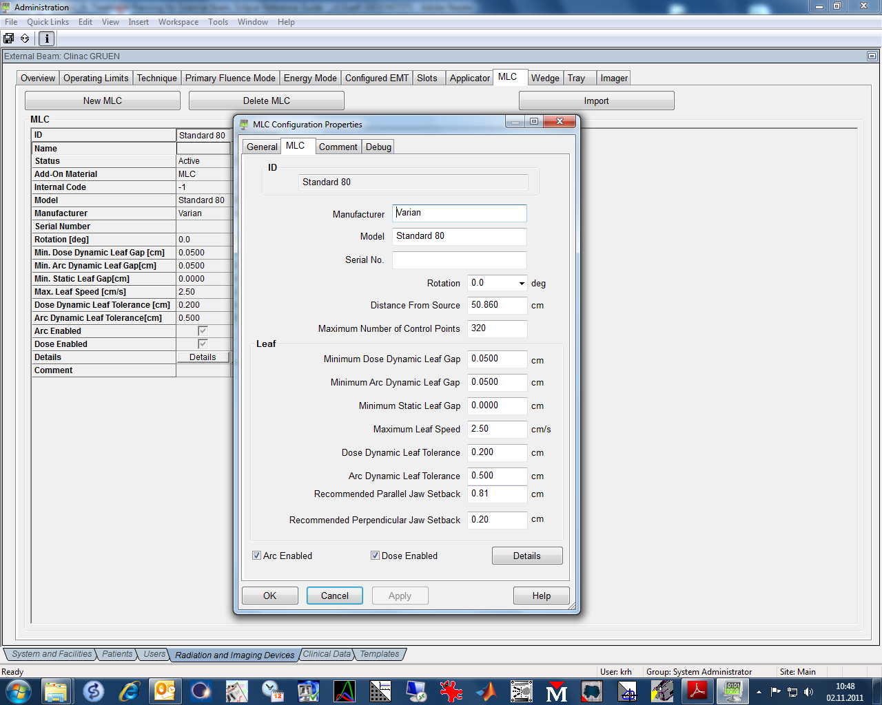
On a Varian linac, the ability to cover closed leaf pairs with the Y-jaws is limited. Since these jaws can only travel overcenter by 10 cm, it is only possible to conform to the open leaf pairs consistently (with the aforementioned 2 mm additional margin) for the central 22 leaf pairs.
This limitation results in additional transmission (through the rounded leaf ends of leaf pairs not covered by the jaws) in channels 1, 2, ..., 9 and channels 32, ..., 40. The planned total dose of the 15MV plan (40 fields) shows the increased leakage.
The suboptimal MLC shielding also shows up in David software. This is the cumulated signal distribution at the end of the 15 MV LRF measurement:
(static image, click to enlarge)
If the Y-jaws were able to follow the opened leaf pairs overcenter right up to the first and last channel, the cumulated signal would be flat over the full field. But since this is a mechanical limitation of the Varian treatment head, there is no way to shield the closed leaf gap in the most lateral channels.
The following animation is a playback of the 40 single segments captured:
(animated GIF, looping forever)
PTW currently requires this kind of measurement for configuration. However, the question is whether this is the best way to model the LRF. Maybe a pre-modelled "generic" LRF (in the form of a simple Gaussian?) would be equally effective. For each combination of linac/energy/David chamber, the LRFs measured by different users should not be very different.
(1)The Y-jaws add 2 mm of margin on each leaf side, which means that the Y-jaws cover 80% of leaf pairs 14 and 16. This reflects the Varian recommendation regarding the perpendicular jaw setback. The parameter value can be found in Administration. For our Standard-80 MLC, the Recommended Perpendicular Jaw Setback is 0.2 cm (the Recommended Parallel Jaw Setback is of no interest for the LRF measurement).