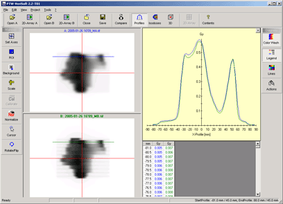
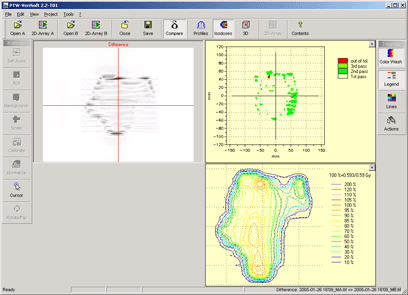
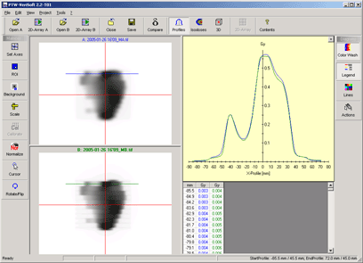
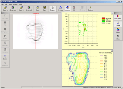
The most comfortable way to do IMRT verification is to use Varian's Portal Dosimetry System. If these software modules are not available, one can nevertheless use the features of Eclipse and the Portal Imaging system itself to do some kind of "Poor Man's" IMRT verification, if some evaluation software, like VeriSoft, is at hand.
Before the detector can be used for dose measurements in the "Poor Man's Approach", it has to be calibrated for dose. In contrast to other dosimetric equipment, all measurements are done in a fixed depth of 8mm. Additional buildup, although technically possible to some extent, is unpractical. Adding backscatter material is not possible.
In contrast to IMRT verification using the 2D-ARRAY, the aS500 can only be used for field verification. Plan verification is not possible, since the beam geometry is fixed (perpendicular beam incidence).
We verify an IMRT plan according to the following steps:
- In Eclipse, we generate a series of verification plans out of the clinical IMRT plan. The system creates five plans if the clinical plan had five IMRT fields. The phantom where the fields are copied to is an artificially created, very simple aS500 detector plate, filled with water. If the DICOM origin of this artificial phantom is placed 8 mm below the surface, the isocenters of the IMRT fields will always be placed there. Therefore, the SSD for these fields is 99.2 cm.
- The dose distribution of the five plans is calculated. The resulting dose distribution will contain the original (= taken from the clinical plan) dynamic MLC sequences and the original field MU.
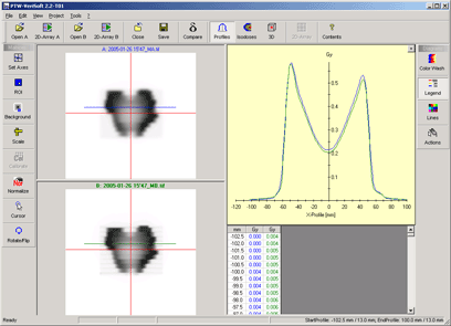
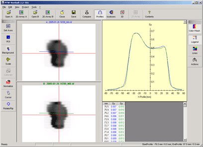
- The dose plane in isocenter, perpendicular to the beam, is exported. This will serve as reference in the later VeriSoft evaluation (the upper left images in Fig.1).
- The dynamic MLC sequences of the IMRT fields are saved as file, since the verification is done in Service mode on the linac, without the use of the verification system (for greater flexibility).
- To compensate for minor setup errors on the linac, and also to compensate for small daily dose deviations from the MU calibration reference (=100 MU give 1 Gy for a 10x10 field in dmax at SSD100), an additional static plan is created: with the same isocenter as the IMRT plans (SSD=99.2 cm), a 10x10 cm open field is planned. The MU needed to produce 2 Gy in isocenter is recorded. Note that the isocenter is in the buildup region of the depth dose curve. With our beam data, 251 MU are needed for 15 MV to give 2 Gy. This reference field is always measured before the IMRT fields, deviations from the target dose of 2 Gy are compensated if necessary. The reference field will also be evaluated with VeriSoft. This completes the preparation phase of the IMRT verification.
The preparation so far takes
about half an hour, depending on the complexity of the plan. On the linac, one
PC runs VeriSoft, always loading the reference dose distribution of the field
to check. The same field is treated, and an integrated image is taken with the
aS500 detector. This DICOM image is saved to a network drive, where VeriSoft
can access it. The evaluation is nearly online. Each field is evaluated before
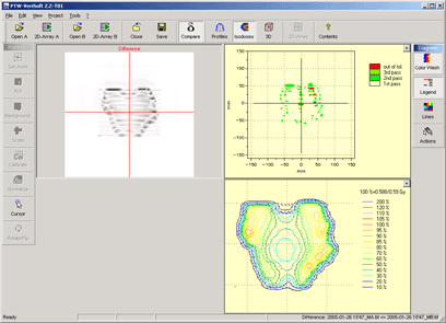
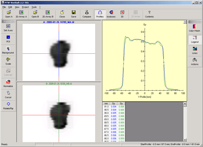
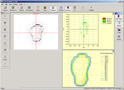
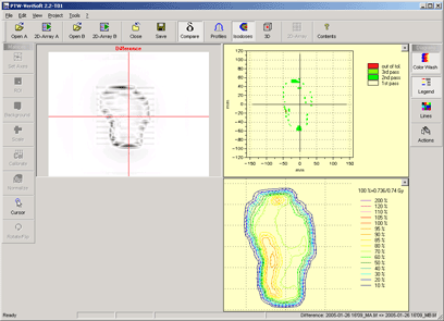
the next field is treated. Fig.1 shows screenshots of a typical five field prostate
IMRT verification.
Field 1 (0°)
