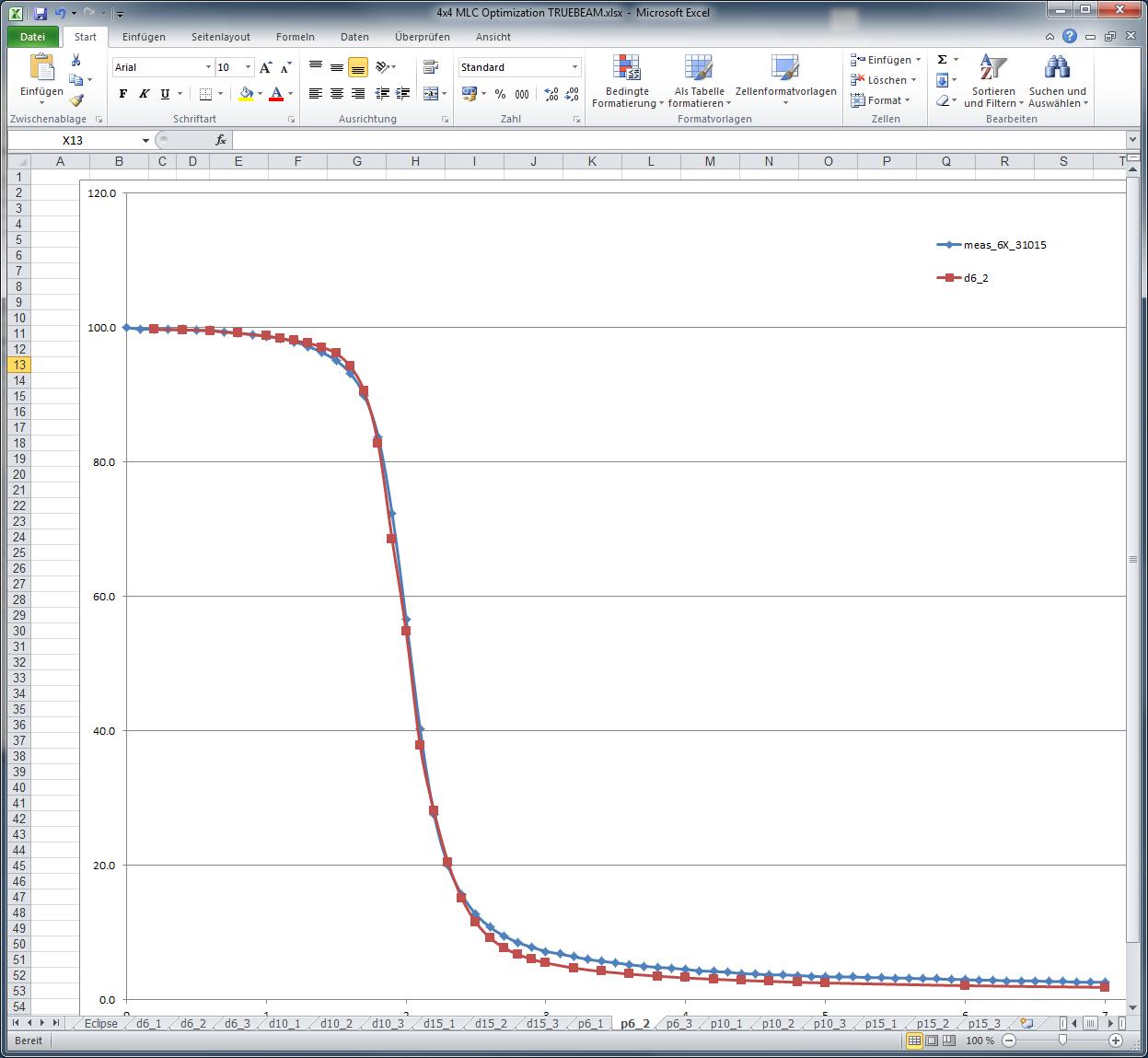
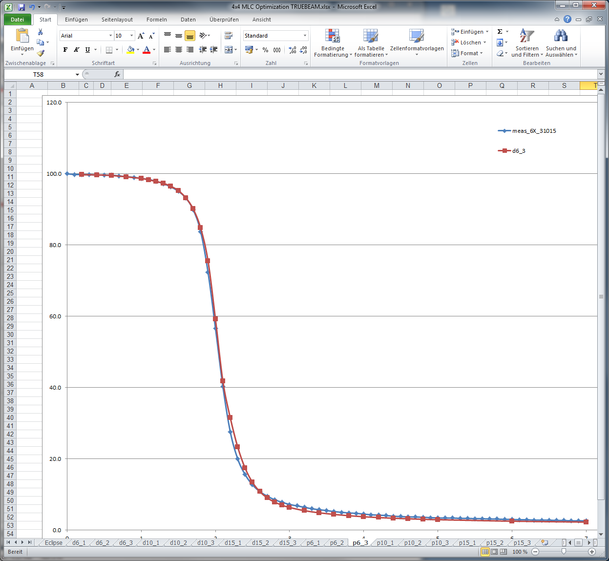

With the introduction of PTW DIAMOND software (version 5.3.2), KFJ broadened its VMAT QA spectrum: Now most VMAT plans1 are verified in three ways before the first clinical delivery: with EPIQA portal dosimetry, Varian Portal Dosimetry, and finally with a DIAMOND calculation2.
In the first 14 months after going clinical with TrueBeam, over 520 arcs were verified using one or both Portal Dosimetry methods (see the results for the first 313 arcs here). Since March 2014, DIAMOND is routinely used. "Older" arcs are retrospectively analyzed, to evaluate the performance of the software.
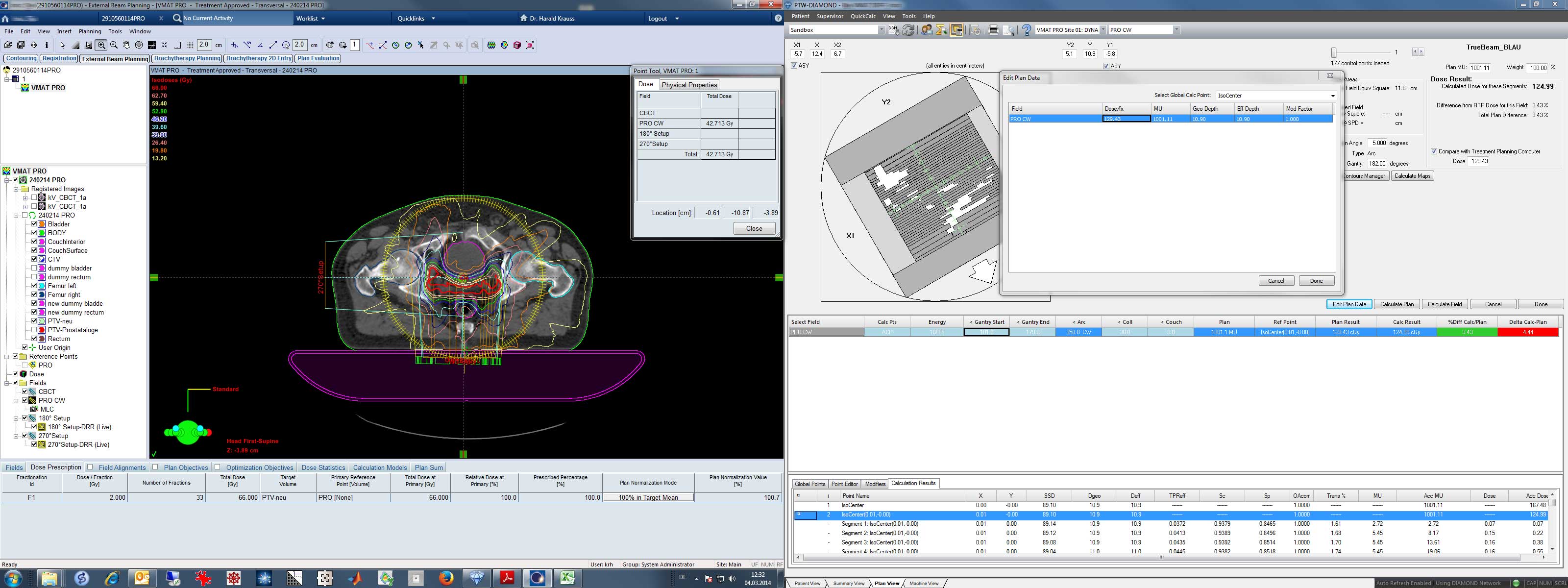
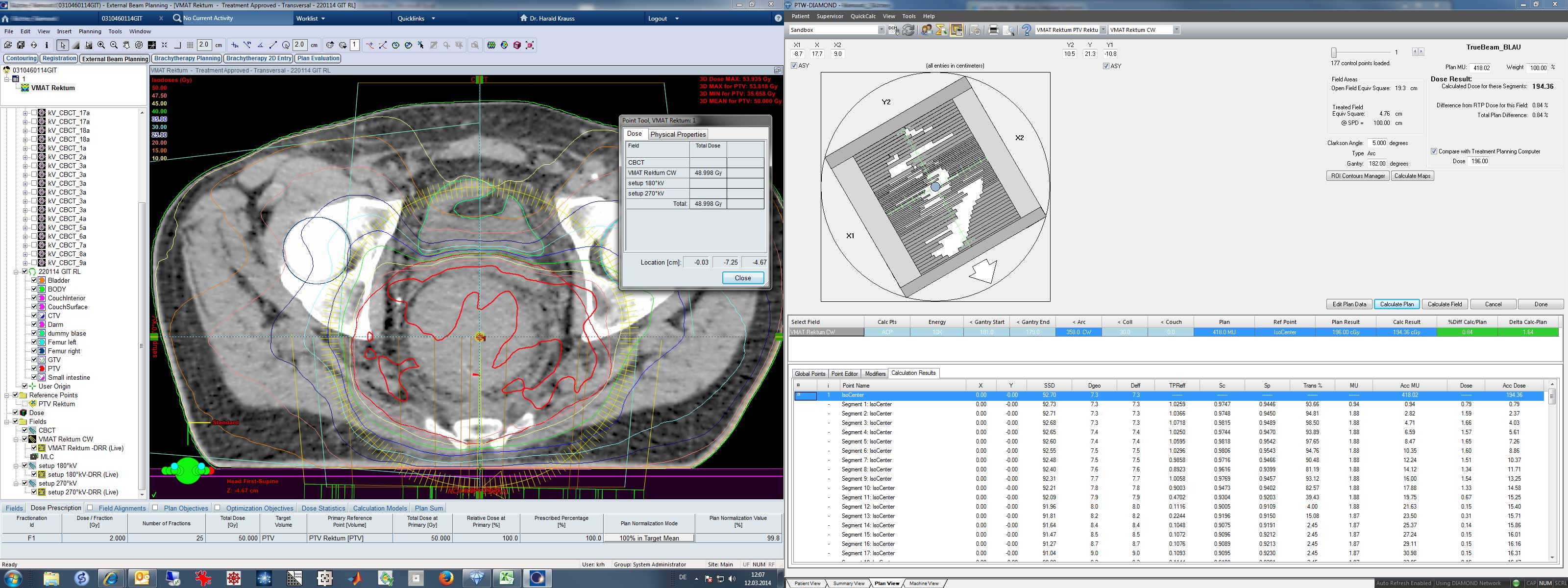
(Left: 10FFF, single arc VMAT Eclipse plan to be verified. Right: DIAMOND calculation result3.)
Introducing DIAMOND
The software can be used for all kinds of plans, static, IMRT (sliding window), and VMAT. Here, we only focus on VMAT calculations.
VMAT Calculation Workflow
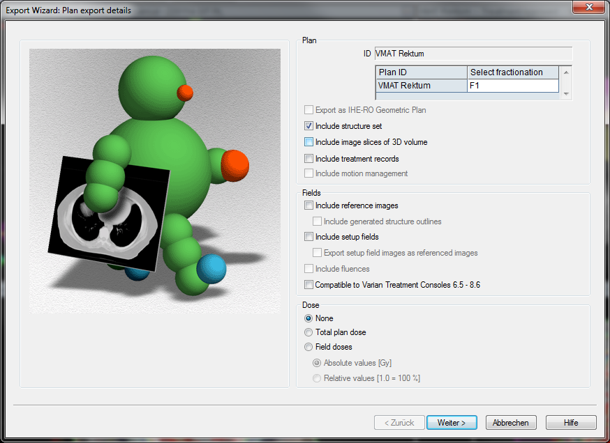
To check a VMAT plan, we do the following: first, we load the plan in Eclipse. In the example, it is a rectum VMAT plan with a single 10MV arc. We right-click on the plan, select Export > Wizard ... and then check "Include structure set" and uncheck "Include setup fields" because setup fields have no associated dose. The structure set is checked because DIAMOND needs it for the calculation of depth and densities.
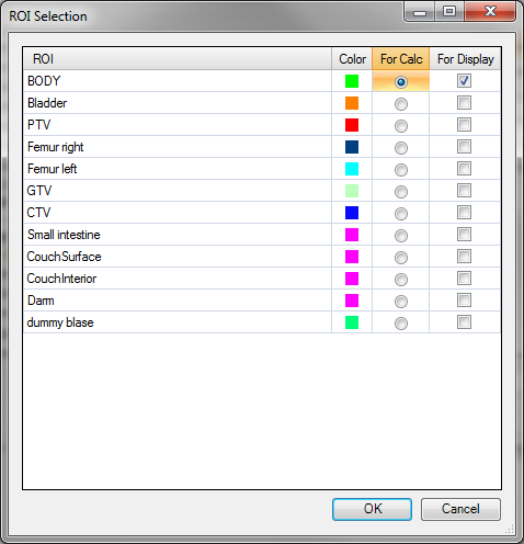
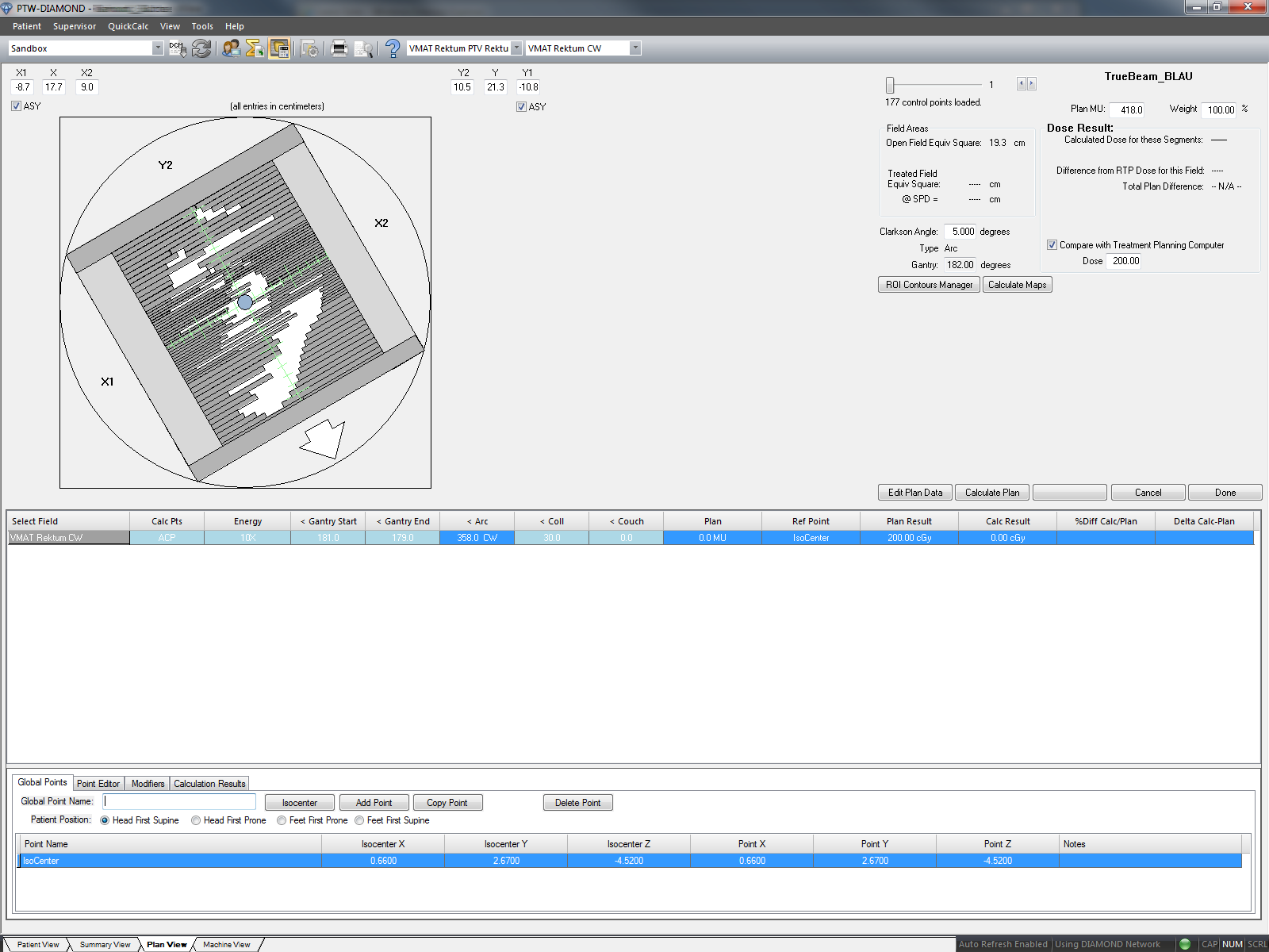
In DIAMOND Patient View, we click on the Import button, select the patient, and select both the plan file and the structure set file. The plan file starts with RP, the structure set with RS. The we switch to Plan View to perform the calculation. From the ROI window that pops up, we only select BODY for calc. "For display" is selected automatically. When we switch to Plan View, the uncalculated plan is shown.
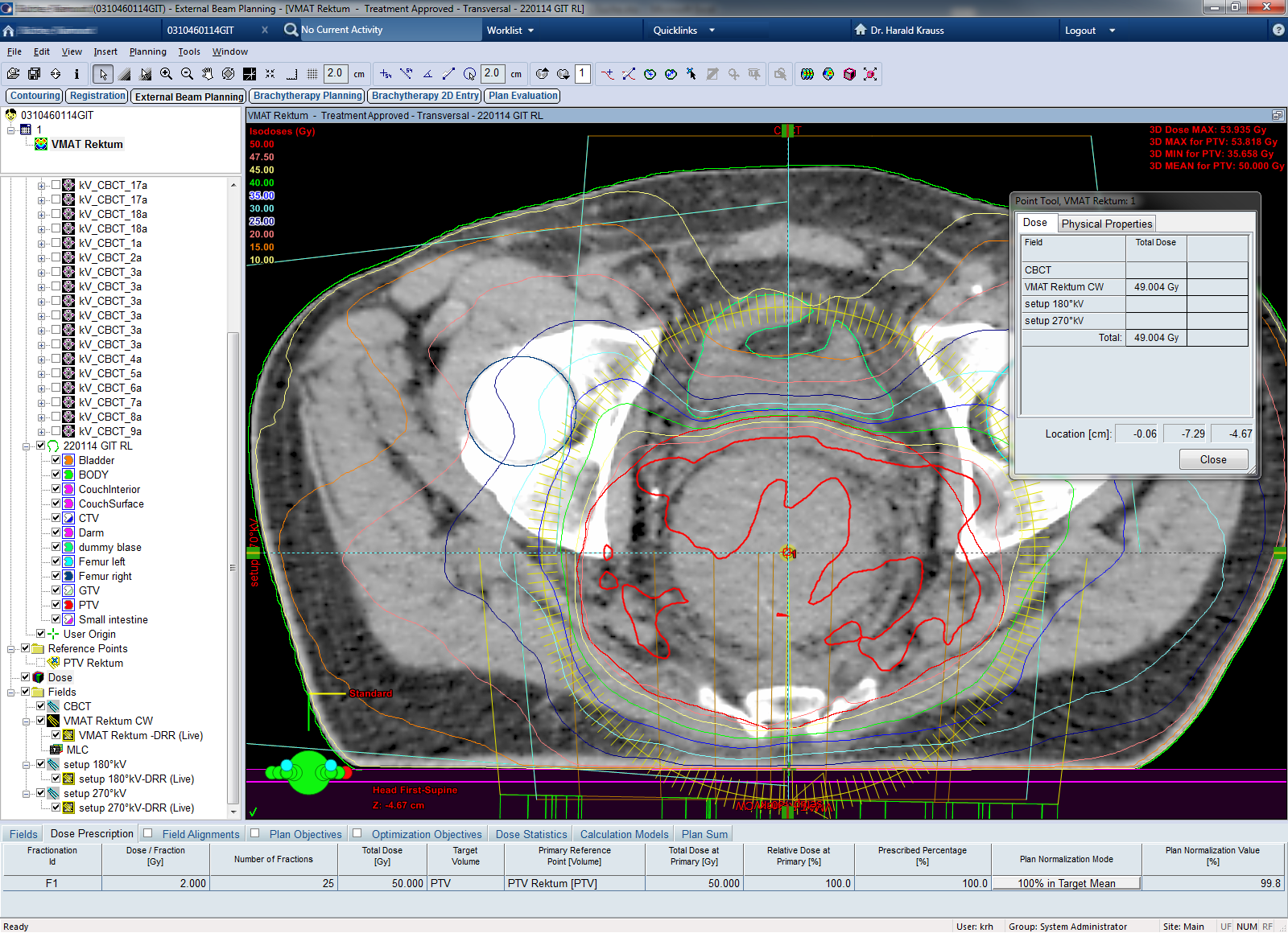
DIAMOND calculates dose in a single point. This is called the ACP, the Active Control Point. If the plan in Eclipse would contain a Primary Reference Point, the coordinates of this point would be contained in the exported plan, and DIAMOND would use this point as ACP. But as we have not assigned a location to the reference point in Eclipse (dose is normalized to Target Mean), DIAMOND will calculate dose in isocenter. In our situation, we therefore have to measure the isocenter dose in Eclipse using the Point Dose Tool4.
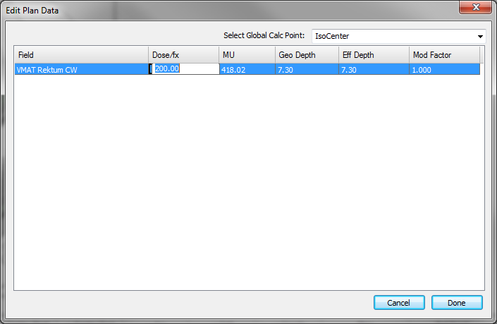
This dose (49 Gy), divided by the number of fractions (25), is the dose per fraction (1.96 Gy). In DIAMOND we click on Edit Plan Data, and replace the nominal fraction dose (200 cGy) by the isocenter dose (196 cGy). Now we can click on "Calculate Plan" (or "Calculate Field", which is the same for a single arc plan), and wait for the calculation result.
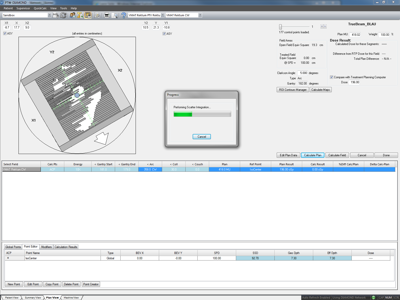
In this example, the calculated isocenter dose is a little less (194.36 cGy) than the Eclipse reference dose (196 cGy). DIAMOND gives the deviation %Diff Calc/Plan with positive deviation (+0.84%) which is a little odd, since Calc (194.36 cGy) is less than Plan (196 cGy). At least the signs can be configured to some extend. For now, we are happy with the result, and always look at the dose values themselves:
This was the typical workflow for most VMAT plans. Head and Neck plans sometimes require one more step on the Eclipse side, at least for us. Since we include all immobilization devices in the Body outline, this means that at isocenter the Body outline is not always a single, closed loop, but sometimes contains two closed loops: the patient plus the carbon base plate of the head support. DIAMOND is not happy with that. It needs a single, closed loop at the Z coordinate of the ACP.
The case is easy to handle. In Eclipse, we first duplicate the Structure Set, then create a Dummy structure that forms a small 3D bridge between the two Body parts that shall be connected (VOI, CT-ranger from -1000 HU to 0 HU, Boolean Algebra: Body = Body OR Dummy). Then we assign this Structure Set to a plan copy of the VMAT plan to be verified. This plan copy is then exported to DIAMOND. Important: it is not necessary to calculate 3D dose of this plan in Eclipse! The reference dose at isocenter is taken from the original plan, which stays untouched.
DIAMOND RS Contours Manager shows the modified Body outline. Note the small vertical bridge in the lower part of the image, that connects the patient ant the support.
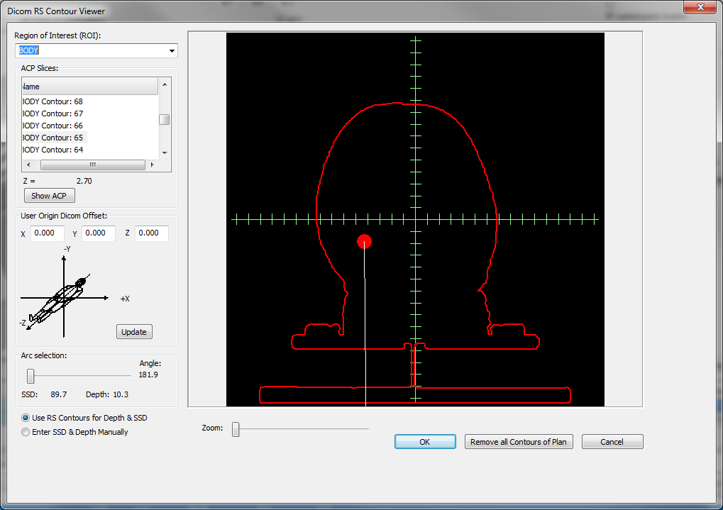
With such a workflow, also the results for head and neck VMAT plans are usually very good:
Challenges
Verification results are not always satisfactory, and sometimes no plausible reason for the deviation can be found. It is easier to guess the reason if large inhomogeneities are present (lung!): DIAMOND calculates in water, and in the current release (5.3.2) the software knows nothing about the density distribution inside the Body outline.
This is the uncorrected calculation result for a plan with two 10MV arcs (going from 181° to 30° and back):
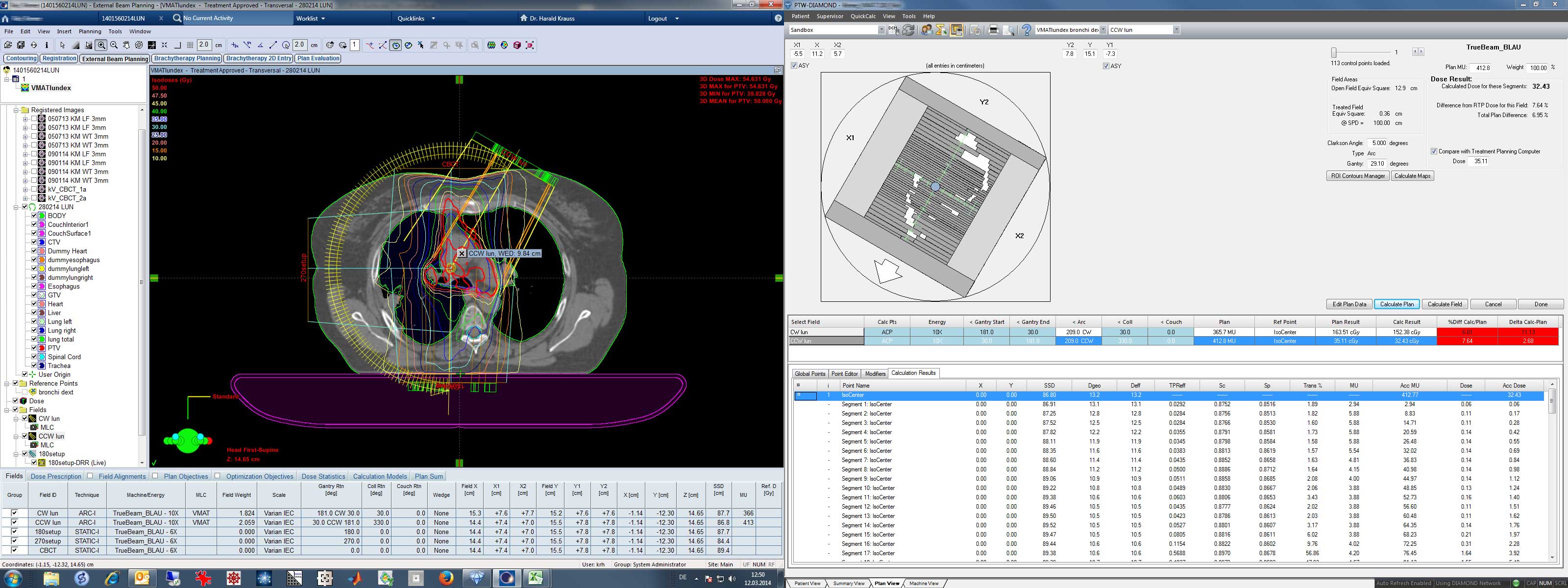
Large portions of the right lung are penetrated by the beam. Deviations are in the range of 6 to 8%. Since calculated dose is lower than plan dose, it can be assumed that the deviation mainly comes from the fact that DIAMOND does not know about the low density lung.
The above screenshot also shows the Eclipse WED tool ("Water Equivalent Depth for Field"). For both arcs, the measured WED of isocenter is 9.84 cm in Eclipse. This is much less than the geometrical depth.
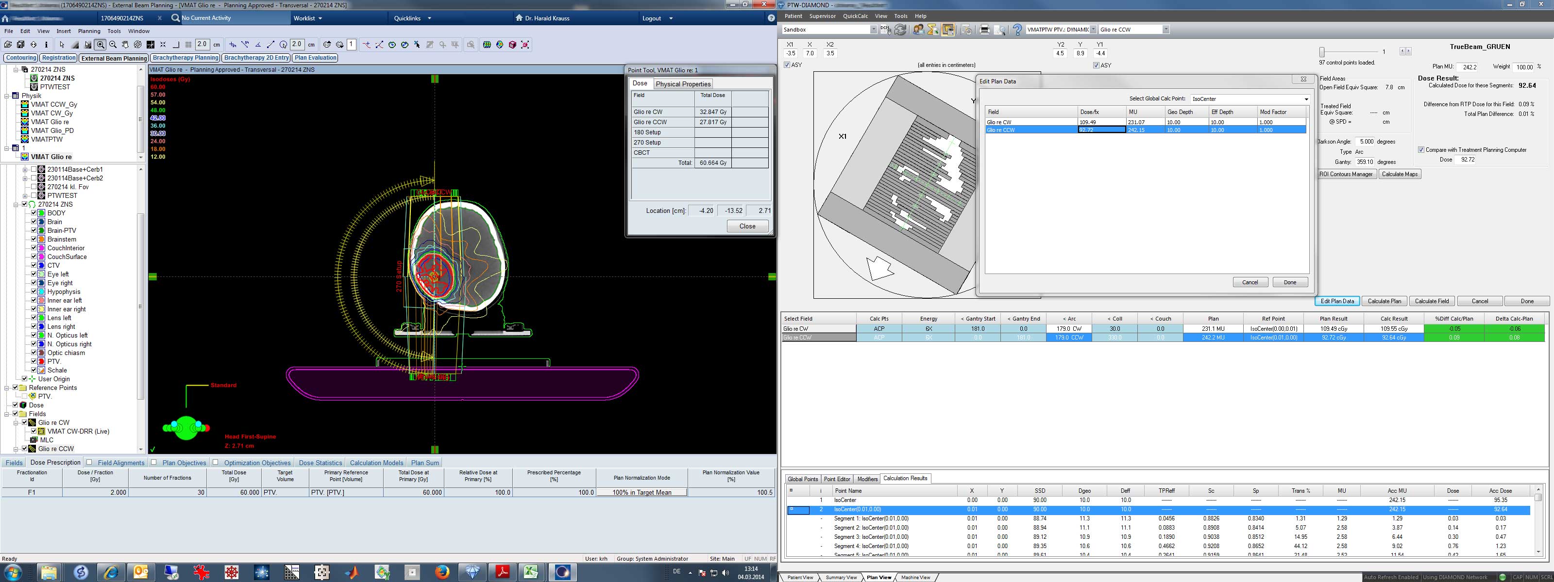
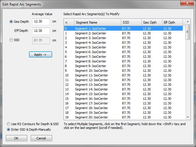
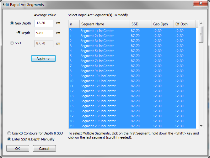
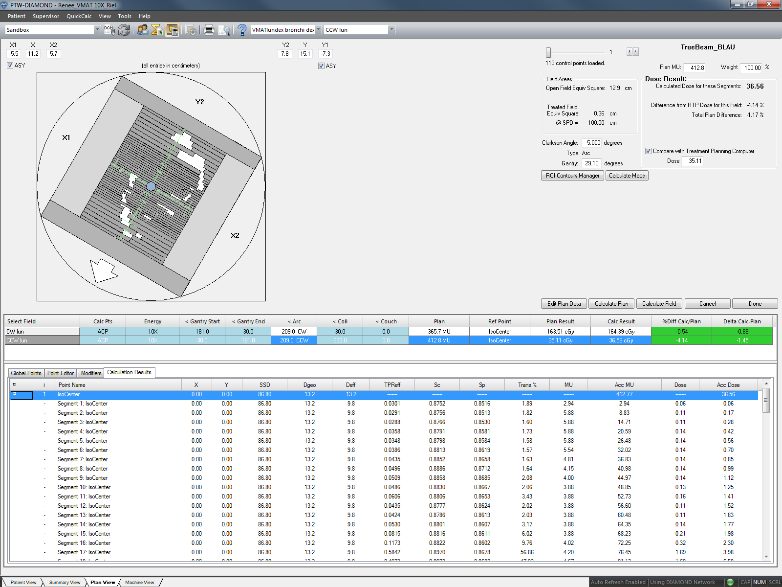
The information can be used to apply a first order correction in DIAMOND. For this, we right-click in Plan View on the IsoCenter point, select "Edit All Points", and get this window. We check that "Enter SSD & Depth Manually" is selected, enter the WED from Eclipse, highlight all segments (could also be a subset), and hit Apply. Then we recalculate the arc, and repeat the procedure for the second arc. The results now look much better:
Conclusions
DIAMOND proved to be a valuable QA tool for VMAT plans, and also for static and IMRT plans (not covered here). As a point dose calculation tool, it has its limitations. However, it is imaginable that under certain conditions, like limited access to the treatment machine, it can replace pretreatment QA measurements. For us, it is currently an additional tool to verify the plans, giving triple confidence that plan delivery is correct5.
Notes
1Since October 2012, VMAT arcs with FFF energies (6FFF, 10FFF) and full dose rate can be verified with EPIQA, but still not with Varian Portal Dosimetry. Although TrueBeam 2.0 now offers separate image calibration of FFF modes (TrueBeam 1.6 simply used the 10MV calibration to acquire integrated images with 10FFF), the necessary Eclipse Portal Dose Image Prediction (PDIP) is still not possible in Eclipse 11.
2 Our fourth method, measurement with the 2D-Array OCTAVIUS 729, is used on a case-by-case basis. For very large fields, where the IDU20 sometimes has problems, satisfactory results can often only acheived with the 2D-Array.
3The use of DIAMOND for flattening-filter free energies is not yet approved by PTW.
4We assume AAA. If plans with more than one arc are calculated with AcurosXB, Plan Dose Calculation should be OFF to use this workflow. Otherwise, the arc contributions to isocenter are not known. Of course, using a Primary Reference Point with a location always works.
5This is not to be confused with plan quality. Even a suboptimal or poor plan can be verified with excellent results.