Basic Validation
Simple Fields
As an example for a simple test case with an interesting result we show a static 15 x 15 cm, 10X field, which enters the phantom at an angle of 128°. This is the angle where the central axis exactly cuts through the edge of the PerfectPitch couchtop, see the Beam's-Eye-View in Eclipse.
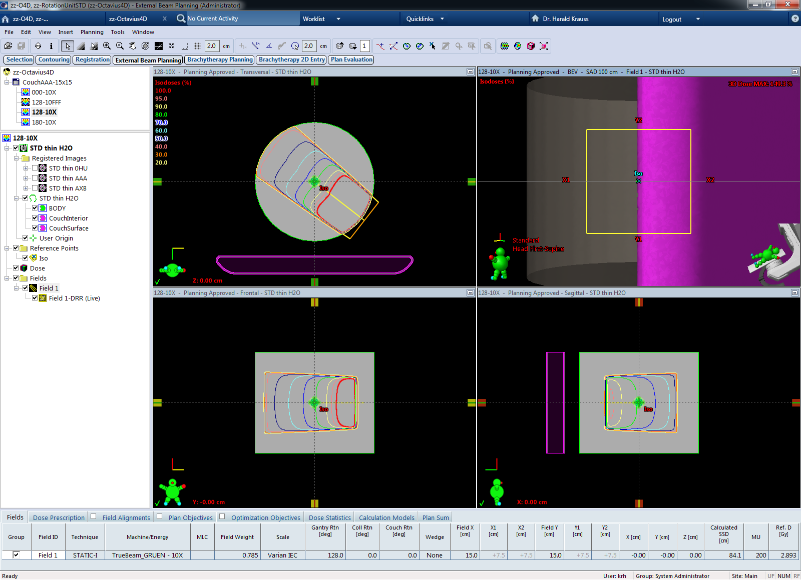
The somewhat larger field size is chosen so that the thin carbon tubes at the bottom of the base unit are also crossed by the beam.
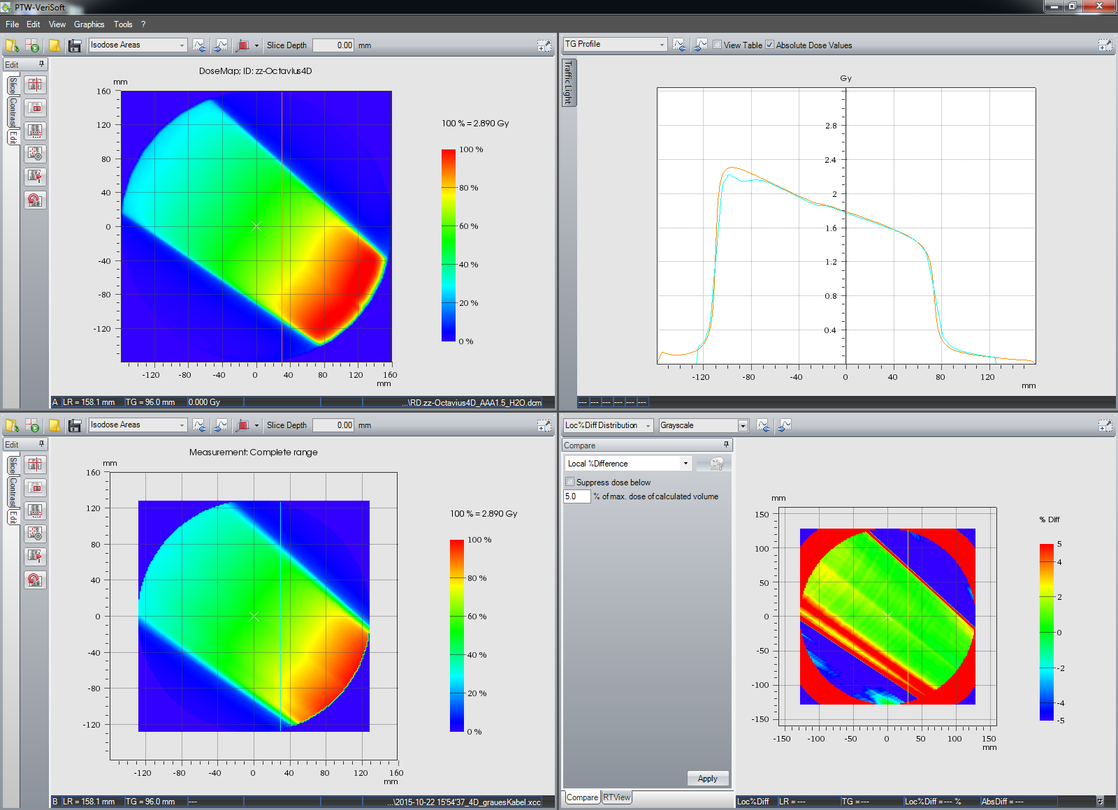
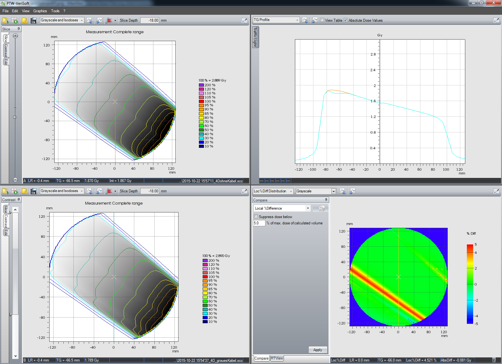
The vertical profile and the local % difference map show a rather large discrepancy in the lower part of the field (the kink in the cyan profile). The 2G2 gamma analysis show that the test fails in this region (cold area in blue):
A visual inspection in the treatment room revealed that not only the carbon tube was in the beam, but also the grey cable which connects Rotation Unit and Control Unit. In Beam's-Eye-View, they were approximately one behind the other. We moved the cable to the other side of the phantom, and repeated the measurement:
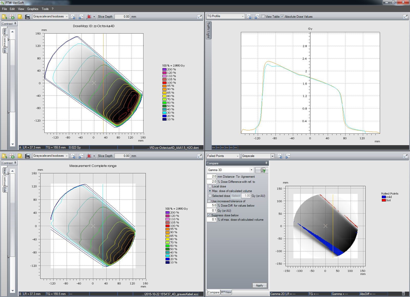
The agreement without the cable running through the 10X beam is now much better. The remaining cold points could be caused by the carbon tube, which natually can't be removed, otherwise the Rotation Unit would fall in two pieces.
Apart from this small disturbance, modelling of the edge of the couchtop in Eclipse is satisfactory. AAA calculation and measurement also agree quite well.
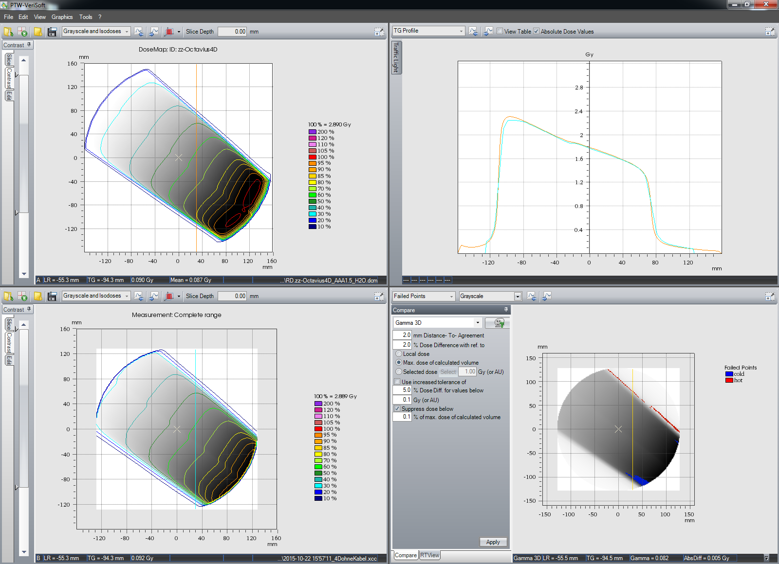
Comparing the two measurements directly even more clearly reveals the disturbance by the cable. Matrix A is the measurement without cable, Matrix B with cable. The "cable effect" leads to a 4.5% local percentage difference:
More Complex Fields
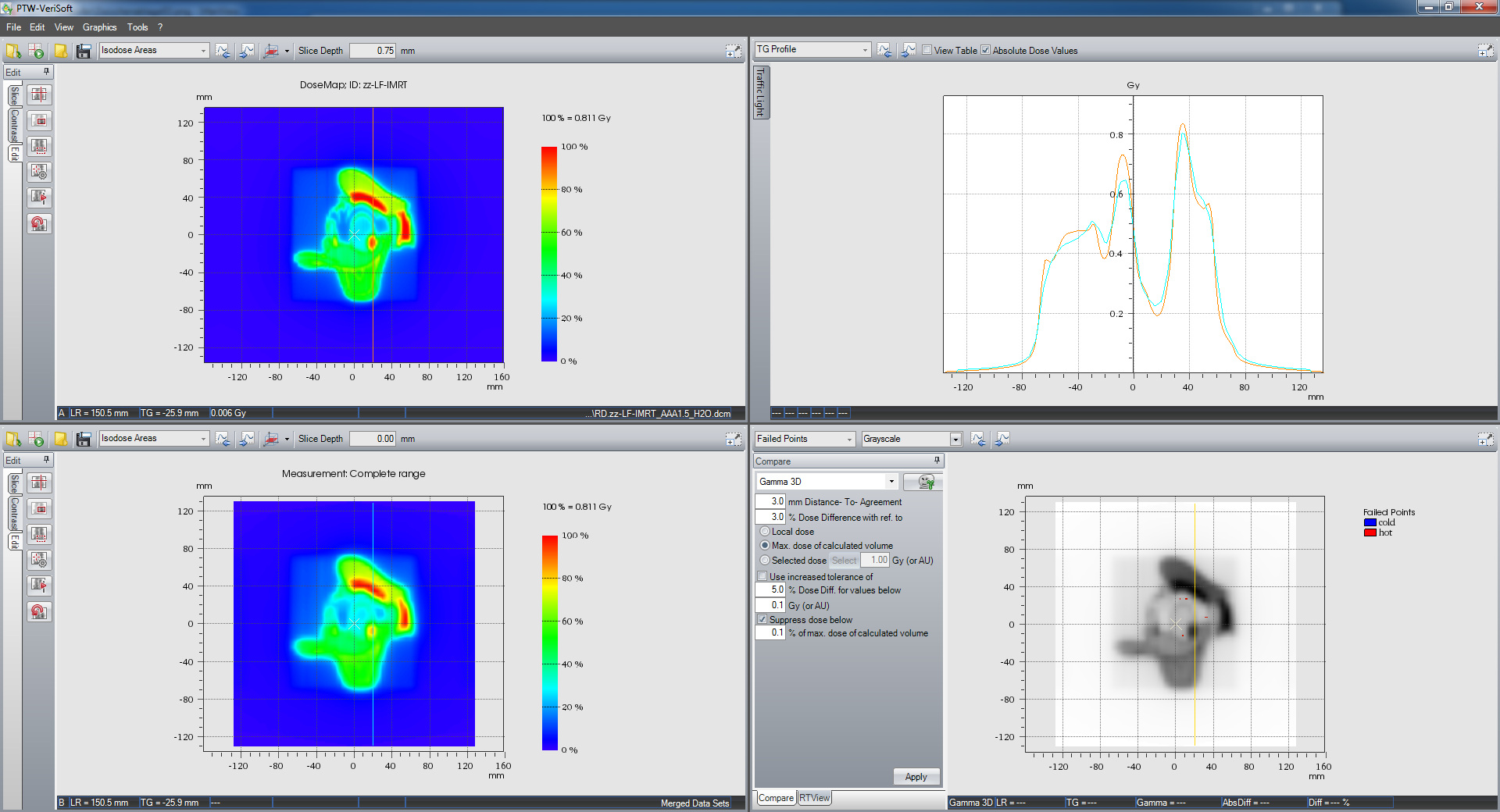
For very small fields, or complex distributions like the following, we usually perform two measurements, and merge them.
The screenshot was taken during the first measurement (the test pattern can be downloaded and imported to a field in Eclipse. It is in *.optimal_fluence format):
The field was a single IMRT field at gantry 0° with 10X energy.
For the second, shifted measurement, VeriSoft expects that the phantom has moved away from the gantry, by exactly 5 mm. With "Goto" on the TrueBeam console, the movement can be done remotely. It is not necessary to enter the room.
After merging the two measurements, the coronal plane is inspected first:
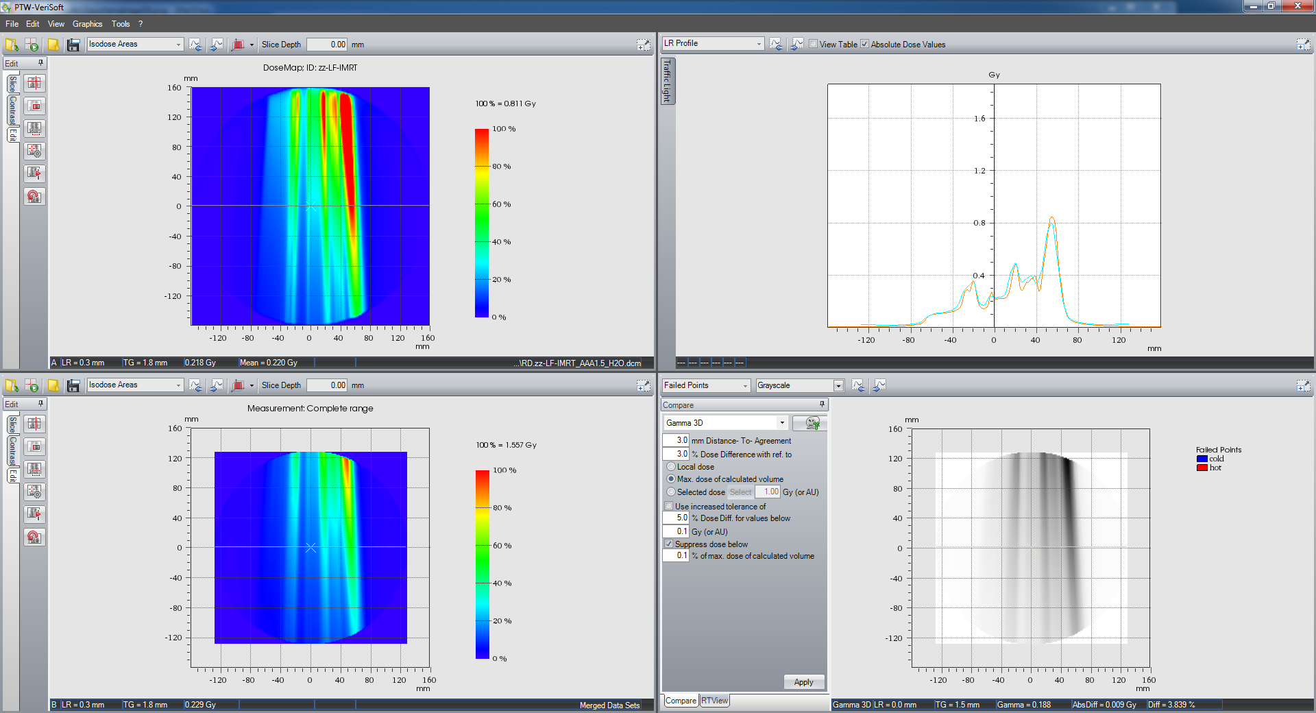
This is a common view encountered with 2D Array measurements. But the amazing thing is that 3D dosimetry offers more views. The transversal plane:
and the sagittal plane:
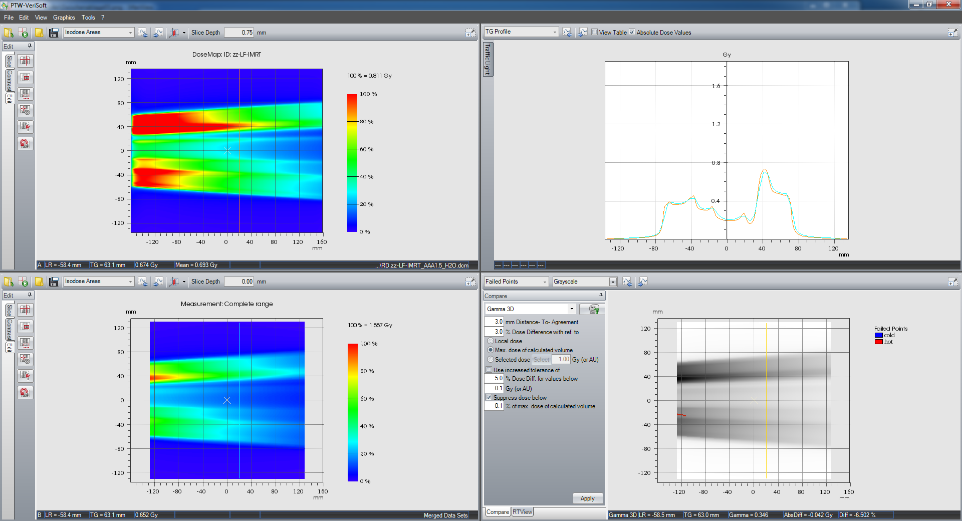
Of course, it is also possible to scroll through the slices. But it is more efficient to perform a volume analysis right away:
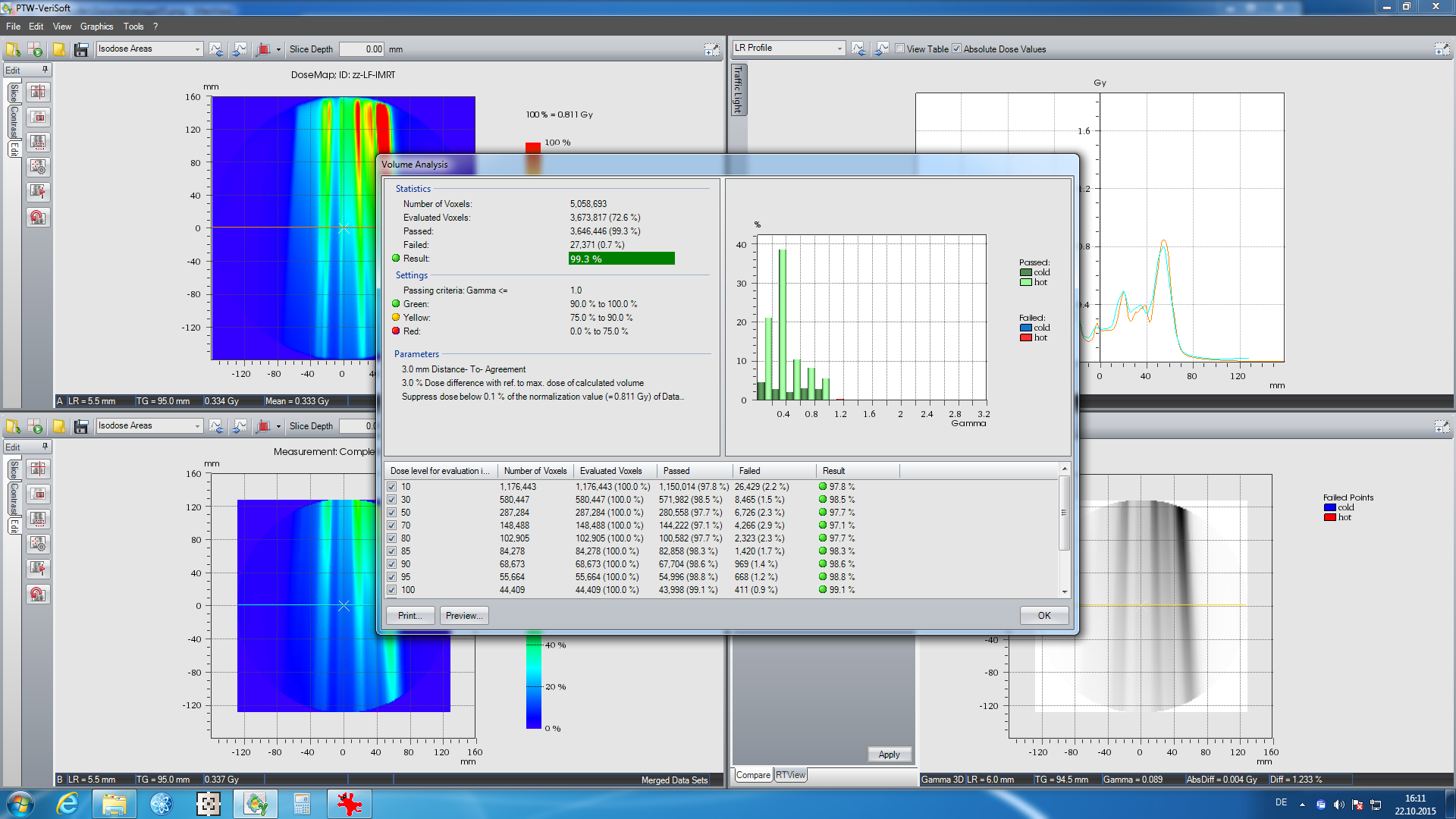
We find the result for 3G3 is quite good, considering the complexity of the test pattern ...