The TPS Phantom
VeriSoft compares two 3D dose cylinders: the TPS calculated dose (usually loaded as data set A) and the Oct4D measured dose (data set B). TPS dose is calculated in Eclipse using a synthetic phantom.
The non-modular Oct4D rotation unit (T40056) comes with a CD (Ref S070024) which contains a synthetic CT scan of the standard size (320 mm) rotation unit.
This CT data set is also valid for the modular Oct4D system with the standard top installed. It can be imported into Eclipse either with or without synthetic couch structure.
The next image shows the original setting for the BODY structure after import from the CD:
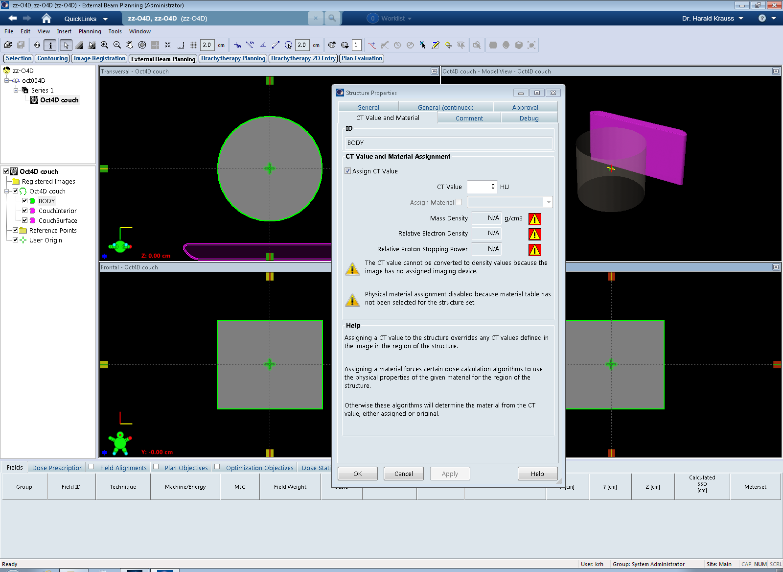
It should be verified that the distance between the BODY and the Couch structures is correct. Detailed information can be found here.
The BODY is set to 0 HU, no material is assigned. This is OK, because assigning a material to a structure is only possible after a Physical Materials table has been assigned to the whole structure set.
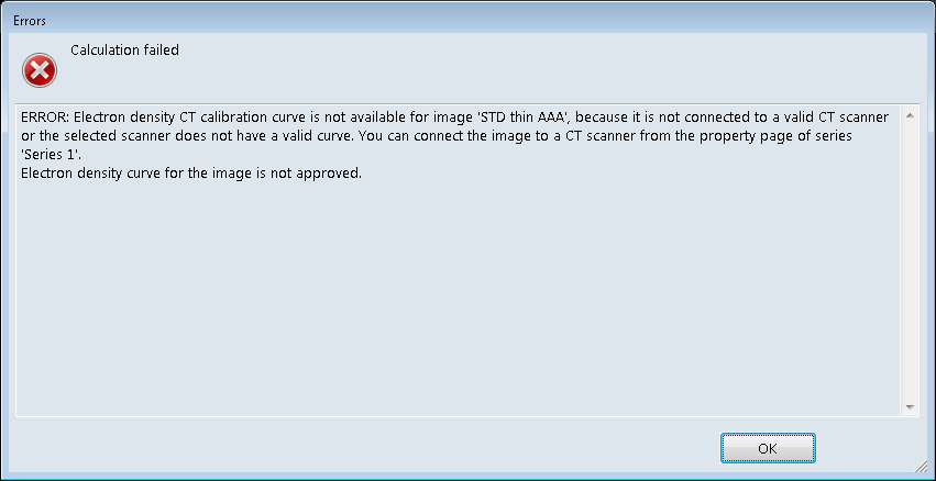
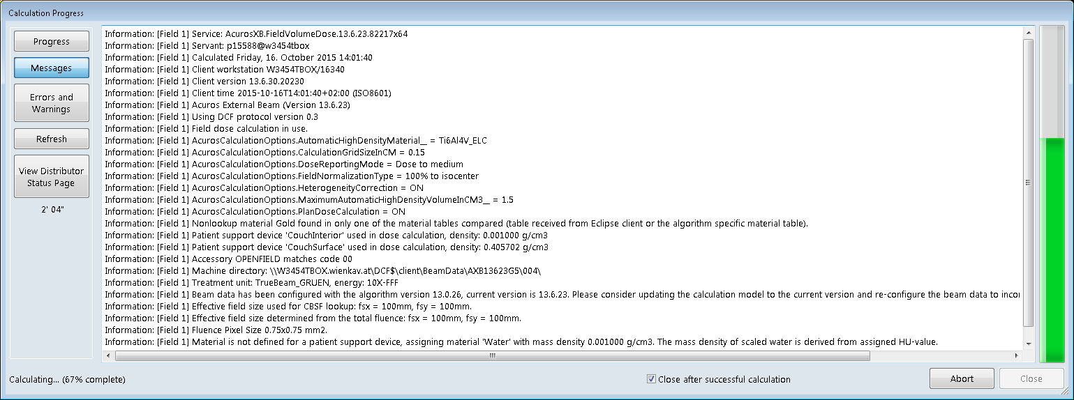
Two selections have to be made to enable dose calculation with AAA and AcurosXB: firstly, an Imaging Device needs to be selected for the imported CT series (see properties of "Series 1"). If this is not done, Eclipse cannot convert HU to relative electron density, because it cannot find an electron density CT calibration curve. Secondly, a Physical Materials table has to be assigned for AcurosXB.
It is not strictly necessary to assign a material to the BODY to make dose calculation with AXB possible. However, if the material is known and appears in the list of physical materials, it is generally a good idea to assign it, in order to keep control about what AXB does. We know the phantom material is polystyrene. If no material is assigned, Eclipse will simply take the 0 HU, select a mixture of physiological materials (water is NOT considered here) and use this mixture for dose calculation.
How VeriSoft Deals with Phantom Density
The Eclipse phantom is very simple, and its CT number defaults to 0 HU. But since the real phantom body is made of polystyrene, the PDD curves which VeriSoft uses for dose reconstruction (and which were measured in water) have to be scaled.
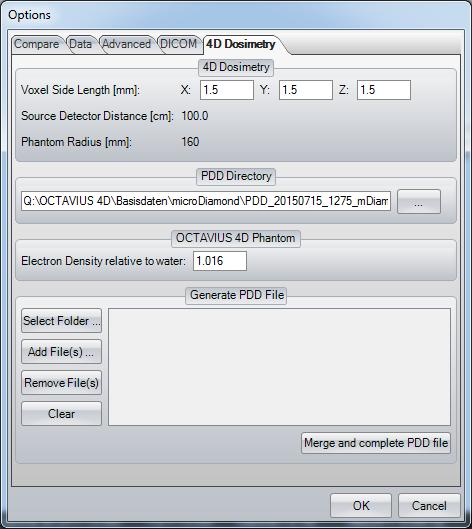
The Options menu of VeriSoft contains several settings for 4D dosimetry. Our default voxel side length is 1.5 mm. This is also the place where the path to the PDD curves can be set. And it shows the value which is used for depth dose scaling. The eletron density of a material relative to water (RED) is important in this context. VeriSoft uses a default RED value of 1.016:
The question now is: should the phantom material also be changed in Eclipse? Or is it fine to calculate 3D dose in Eclipse with 0 HU but measure in a polystyrene phantom?
We will try both approaches and investigate whether one is bether than the other. Keep in mind that if cross-calibration is performed at the beginning of each measurement session, dose at isocenter for a 10x10 field will always be "correct", because this is the cross-calibration point.
The PTW Code of Practice suggests that the TPS phantom is either set to RED = 1.016, or the mass density to 1.05 g/cm3. This is what we did in Phantom I for AAA, and Phantom II for AcurosXB.
TPS Phantom I: Matching RED Values for AAA
For AAA, the Relative Electron Density (RED) is important. In Eclipse, RED cannot be set directly. Instead, we set the HU value of the BODY until the corresponding RED matched the VeriSoft value as closely as possible:
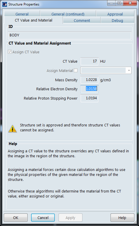
It turns out that 17 HU are necessary to get the best agreement (the Code of Practice cites [Thomas 1999] with a value of 16 HU, which is very close). However, the absolute value is rather meaningless because it depends on the institution's electron density calibration curve.
Using 17 HU for the BODY in our case makes sure that VeriSoft reconstruction and AAA dose calculation use the same scaling of depth dose curves.
This structure set in Eclipse is called STD thin AAA.
TPS Phantom II: Matching Mass Density for AcurosXB
Acuros uses mass density, not electron density, to calculate dose. A mass density calibration curve must exist in Eclipse, otherwise dose calculation is not possible.
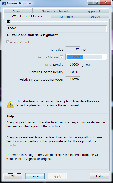
Fortunately, PTW and Varian agree1 that the material polystyrene has a mass density of 1.05 g/cm3. Assigning this material to the BODY therefore immediately gives the correct mass density with a CT number of 37 HU (the value is depending on the mass density calibration curve):
This structure set is called STD thin AXB.
With the two structure sets STD thin AAA and STD thin AXB, we measured during the first three months. Then we switched to the much simpler approach:
TPS Phantom III: One Phantom for Both Algorithms
We created a third structure set and set the BODY to 0 HU (the default setting on the PTW CD). For use with AAA, no material can be set.
For AXB, we have to answer two questions:
- Should we additionally assign the material water to the BODY?
- Do we want to report dose to medium (D2M) or dose to water (D2W)?
- Do we want to have k(AXB) = k(AAA) during measurement?
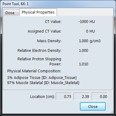
Question 1 sounds strange, but 0 HU does not automatically mean water, at least not for Acuros. During CT to material mapping, AcurosXB will convert CT numbers to physiological materials, and water is not on the list. If the BODY is assigned 0 HU, Acuros will use for dose calculation the material composition of 97% skeletal muscle and 3% adipose tissue. Assigning the material water to the BODY therefore gives slightly different dose.
With the following table of reference doses (dose in Gy for a static 10x10 cm field with 200MU), the questions can be answered. The table contains the doses at isocenter calculated on the Oct4D phantom for different algorithms, BODY settings, dose reporting modes and energies:
| Alg. (BODY, Reporting Mode) | 6X | 10X | 15X | 6FFF | 10FFF |
|---|---|---|---|---|---|
| AAA (0HU) | 1.266 | 1.493 | 1.590 | 1.152 | 1.374 |
| AXB (0HU, D2M) | 1.252 | 1.478 | 1.570 | 1.146 | 1.367 |
| AXB (0HU, D2W) | 1.269 | 1.497 | 1.590 | 1.160 | 1.385 |
| AXB (H2O, D2M) | 1.259 | 1.488 | 1.582 | 1.151 | 1.376 |
| AXB (H2O, D2W) | 1.259 | 1.488 | 1.582 | 1.151 | 1.376 |
Dose values were calculated with algorithms version 13.0.26 and 1.5 mm grid. "H2O" means that the material water was assigned to the BODY. For AXB, the dose reporting mode (D2M or D2W) is also specified.
The table shows that k(AXB) = k(AAA) only appears once, for 15X and 0HU/D2W. This is a coincidence at this specific geometry (field size, depth).
Choosing to report D2W would mean that every time we generate an AXB verification plan in Eclipse, we would have to change the calculation options setting. For clinical plans, we use D2M. Therefore, the verification plan would also be set to D2M per default. The need to change the options setting every time is too inconvenient and a source of error. The answers to the questions thus are:
- Yes (does not hurt with AAA, and clarifies which material is used with AXB).
- D2M, because this is the setting for clinical plans.
- No.
If one calculates the percentage difference of AXB doses relative to AAA, one gets the following table:
| Alg. (BODY, Reporting Mode) | 6X | 10X | 15X | 6FFF | 10FFF |
|---|---|---|---|---|---|
| AAA (0HU) | 0 | 0 | 0 | 0 | 0 |
| AXB (0HU, D2M)* | -1.1* | -1.0* | -1.3* | -0.5* | -0.5* |
| AXB (0HU, D2W)* | +0.2* | +0.3* | 0.0* | +0.7* | +0.8* |
| AXB (H2O, D2M) | -0.6 | -0.3 | -0.5 | -0.1 | +0.1 |
| AXB (H2O, D2W) | -0.6 | -0.3 | -0.5 | -0.1 | +0.1 |
*AXB (0HU) doses are not comparable to AAA (0HU), because AXB here uses a mixture of muscle and adipose tissue, whereas AAA effectively uses water.
The differences between AAA (0HU) and AXB (H2O) are not systematic, and probably depend on how good the algorithms transform the same measured beam data into the respective beam model during beam modelling. Although measured beam data (the input) was the same for AAA and AXB, the agreement of measured and calculated curves in beam analysis is different for AAA and AXB.
Now we have the most convenient setting for the BODY in the "general purpose structure set": it has 0 HU, material "water" assigned, and we report D2M for Acuros plans. The names for this structure set are:
- STD thin H2O (for the Standard top and the thin IGRT couchtop)
- SRS thin H2O (for the SRS top and the thin IGRT couchtop)
A comparison of the clinical results for TPS Phantoms I/II and TPS Phantom III can be found here.
Notes
1If a material listed in the Physical Materials table of RT Administration is allowed to have a range of different densities, then the HU value can be changed after the material is assigned, otherwise not (PMMA, PEEK, ...).