Material and Methods
CT Scan of the Octavius Phantom
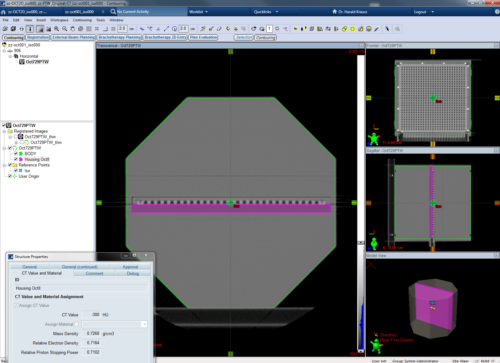
We imported the PTW dataset from the PTW website, and imported it into Eclipse (Patient-ID: zz-oct001_iso000). As imaging device we assigned our Toshiba AquilionLB CT scanner, to avoid the generic CT calibration curve. The two PTW structures were also imported. "Housing OctII" was used with the recommended -300 HU assignment.
We also acquired an own CT scan of the OD/OP tandem on our AquilionLB ("KFJ scan"), with the following scan parameters:
- 120 kV, 400 mA, 1 s per revolution
- Calib-FOV "LL" (550 mm) , zoomed to 400 mm
- Collimation 1.0 x 16, pitch factor 0.687
- Reconstruction kernel FC70 (technical kernel), image thickness 1 mm
These settings give a scan with low image artefacts and high spatial resolution.
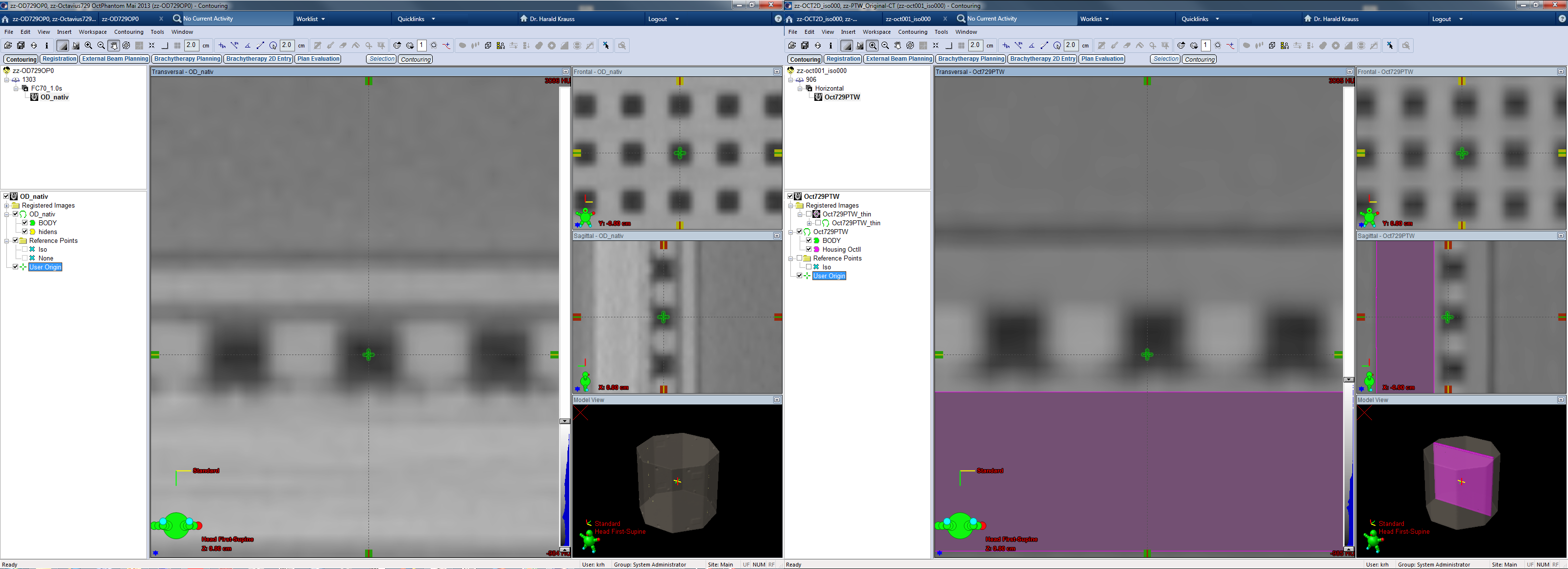
The OD/OP tandem was scanned in two orientations: 0° (with the OD placed horizontally) and 90° (with the OD in vertical orientation), and imported in Eclipse (Patient-IDs: zz-OD729OP0 and zz-OD729OP90).
Couch structures were added on all three phantom patients (Varian Exact IGRT Couch Top, thin, using default HU assignments -300 HU for the Panel Surface and -1000 HU for the Panel Interior).
Post-Processing and Contouring
To make dose calculation with AcurosXB possible, high-density voxels (mass density above 3.000 g/cc) have to be segmented. The material Stainless Steel was assigned to these voxels. This has no impact on dose calculation, since the affected voxels are either inside the phantom's feet (which are only used in the 90° setup), or small cable segments of the Array's electronics. Both are far away from any treatment field.
The BODY structure is the most important structure, since it is the region which is considered for dose calculation and attenuation. The BODY structure of the KFJ scan was automatically generated by Eclipse using a threshold setting: all voxels with HU values larger than -350 HU were considered as Body. This is also the setting for clinical scans.
To be able to compare local dose to the mean dose in the OD's ion chambers, chamber 365 (the central chamber of the matrix) was segmented separately as a 5 x 5 x 5 mm cube in 5 successive slices (structure "C365").
Eight Structure Sets were created for the 0° setup of the KFJ scan, and one for the the PTW scan:
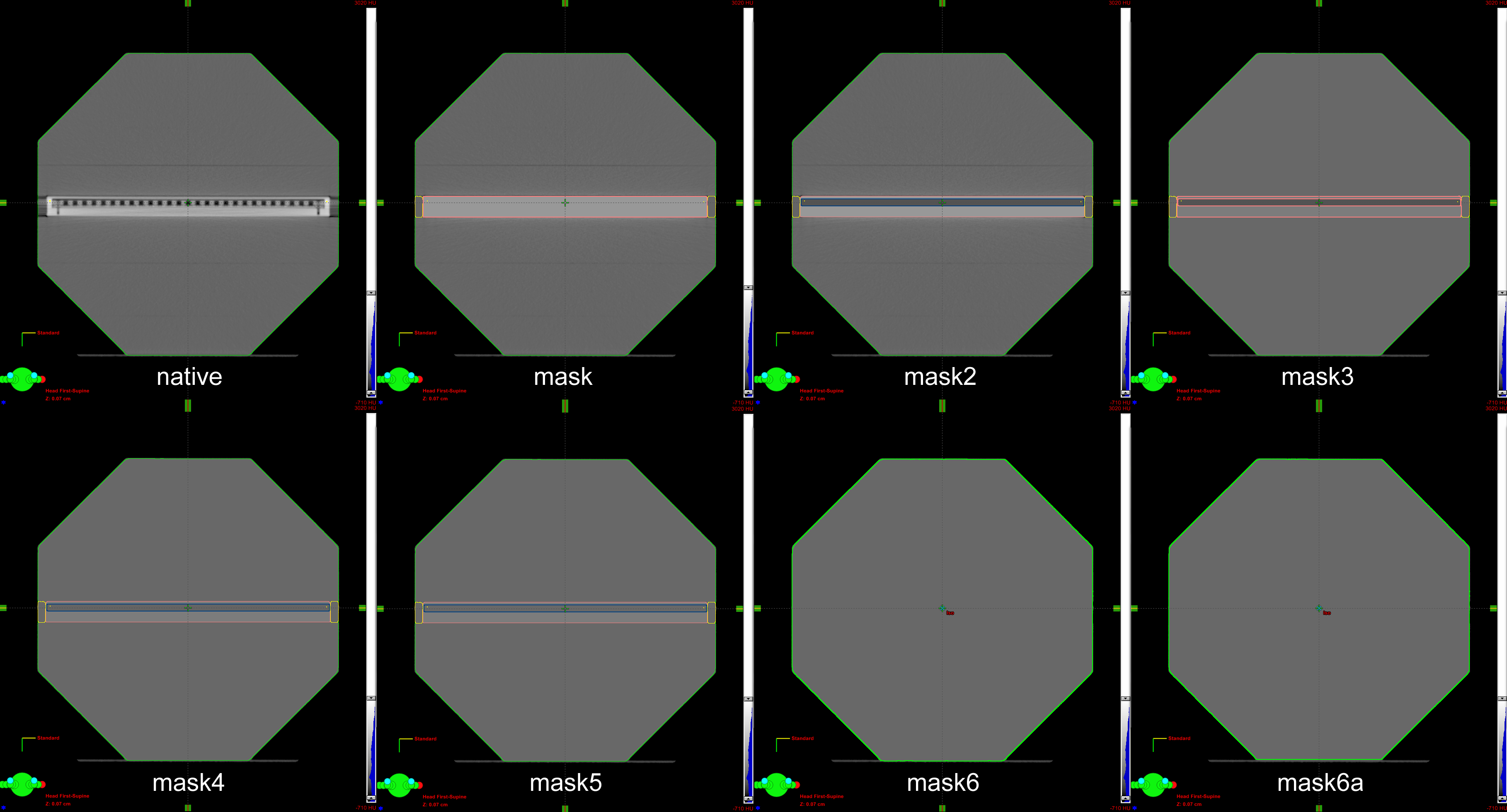
(Fig.2: The eight KFJ structure sets of the OD/OP tandem - one native and seven masked.)
- "native": contains the original KFJ CT data. Only a few high density voxels were segmented separately, to enable AcurosXB dose calculation.
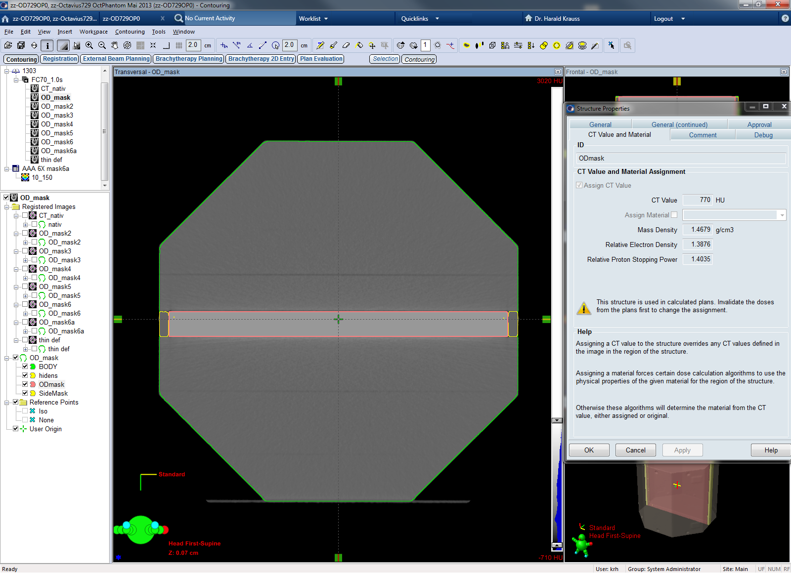
- "mask": the whole OD (housing plus interior) is set to a homogeneous 770 HU (which is the HU-average over the whole OD). The sides are set to 10 HU (to compensate imaging artefacts).
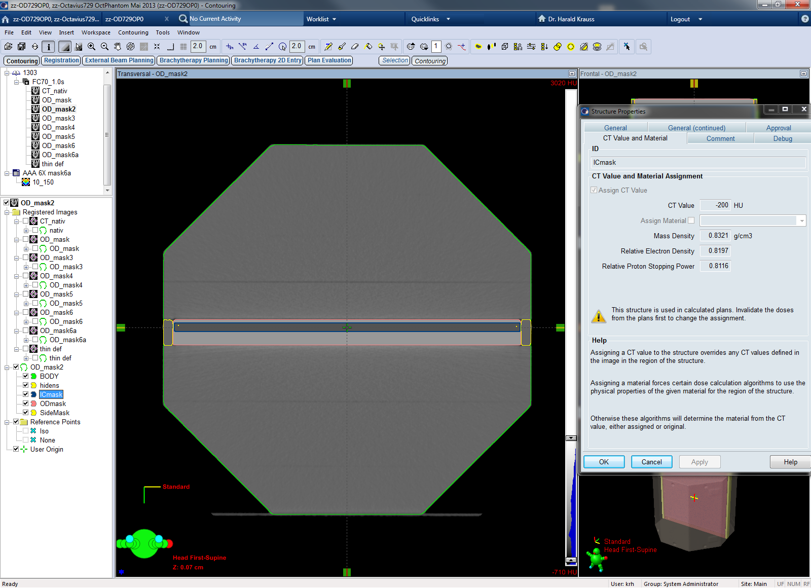
- "mask2": same as "mask", but the plane of the ionization chambers is separately segmented and set to -200 HU.
- "mask3": the whole OP ("BODY") and the sides are set to 37 HU and the material Polystyrene is assigned. The OD housing is set to 315 HU (material: PMMA). Chambers are still -200 HU.
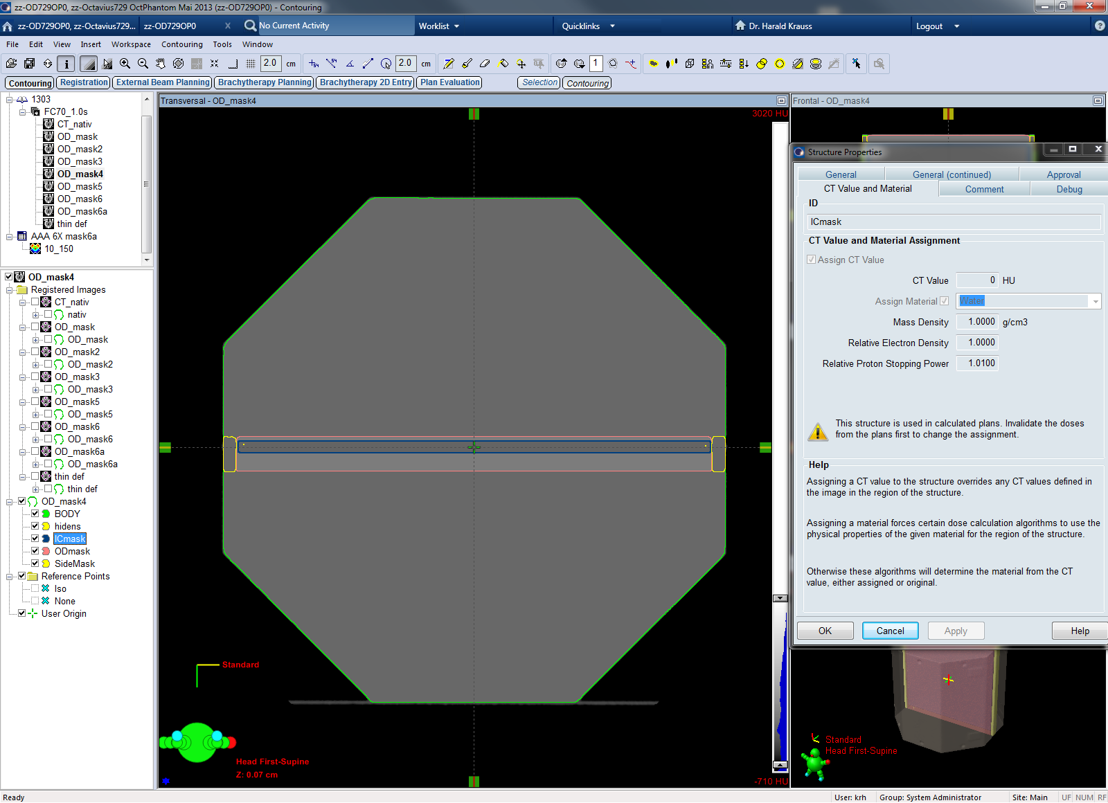
- "mask4": Same as "mask3", but the chambers are set to 0 HU (Water).
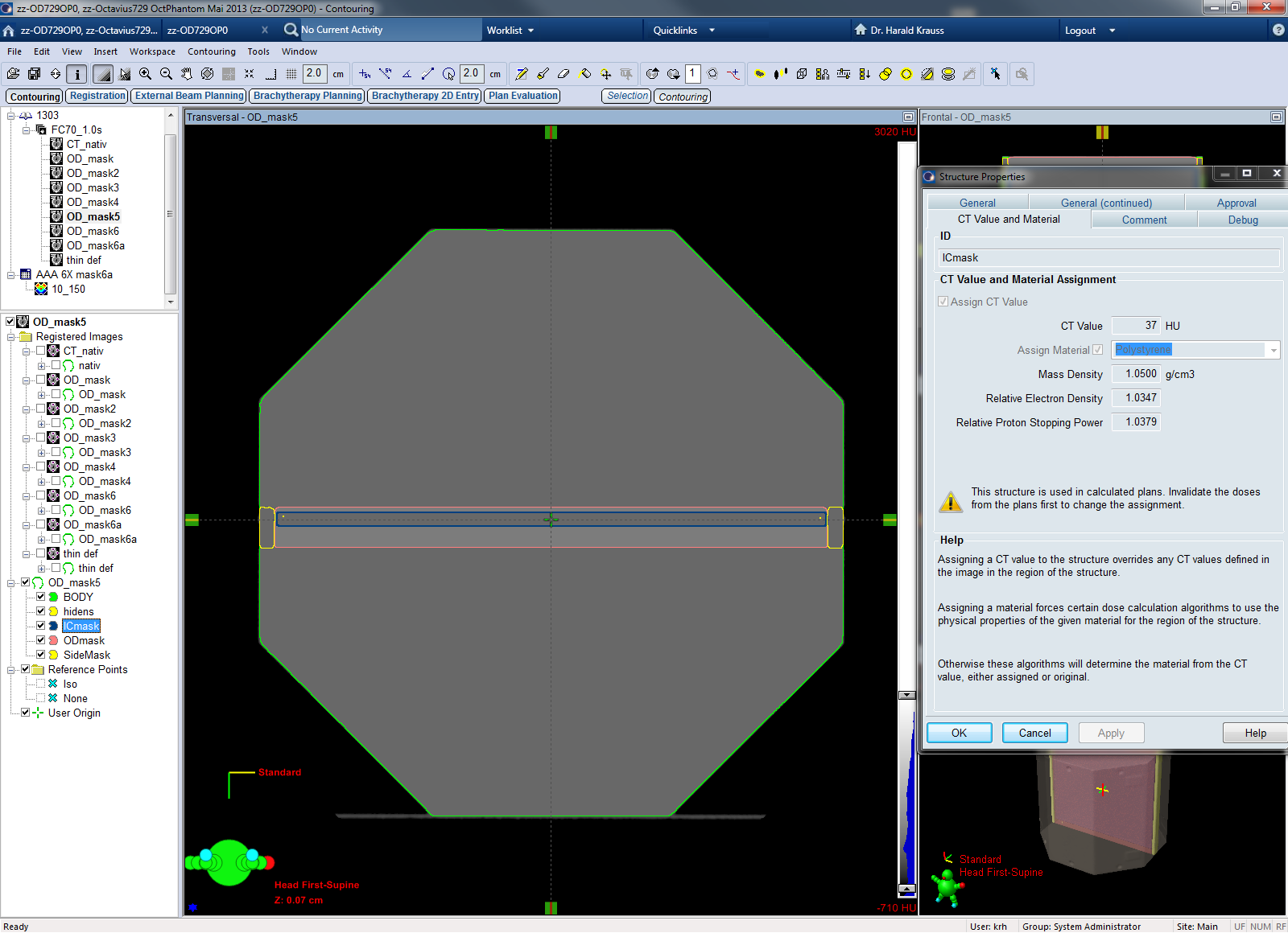
- "mask5": The chambers are set to 37 HU (Polystyrene). Now there are only two different HU-values: 315 HU (PMMA) for the housing of the OD, 37 HU for the rest.
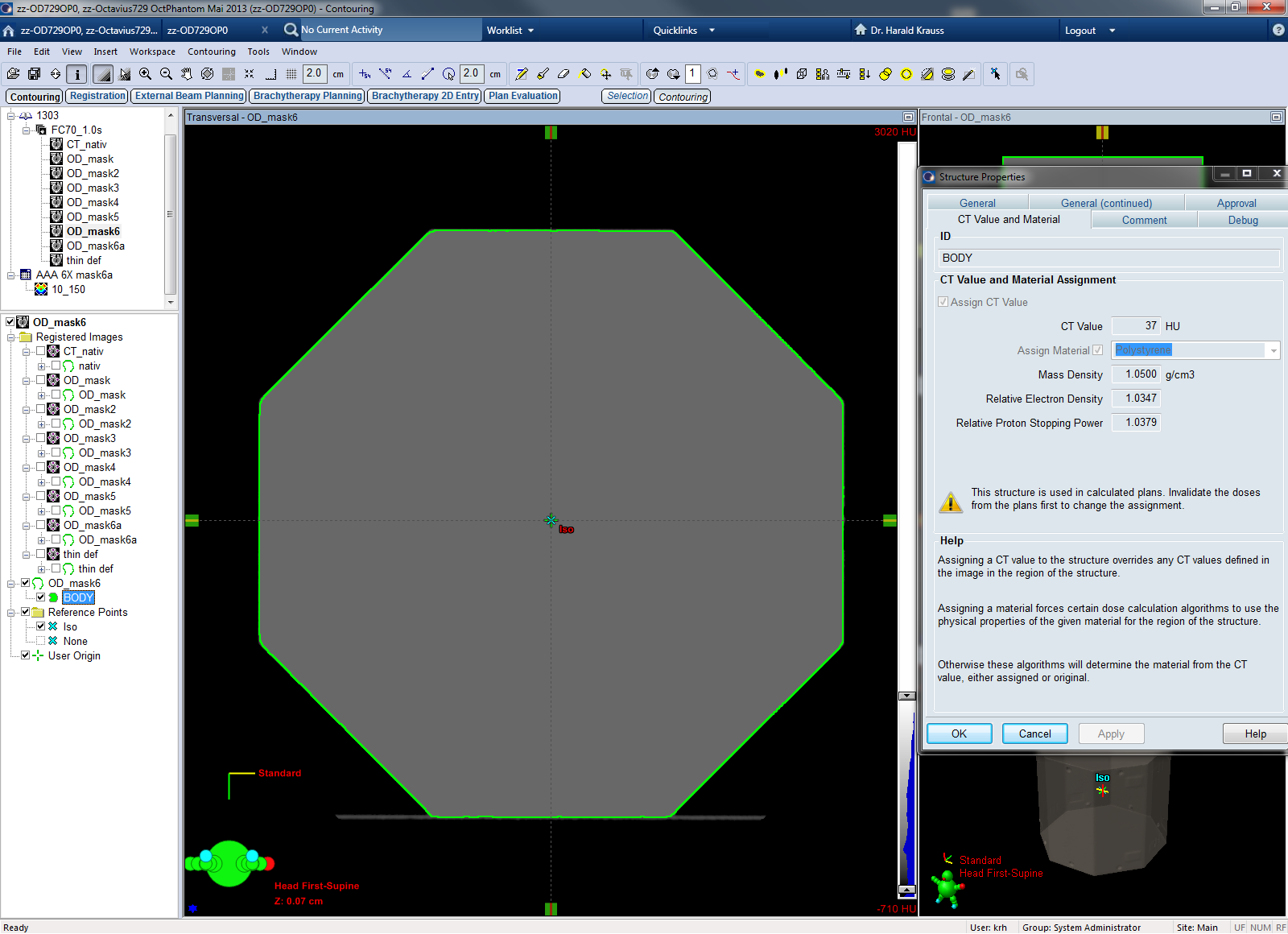
- "mask6": as a final simplification, the housing is removed. The whole setup is now a homogeneous volume filled with 37 HU.
- "mask6a": the BODY is cropped by 2 mm at the bottom. See text for an explanation.
- "OCT729PTW": CT data, BODY and Housing OctII are as downloaded from the PTW website.
In the KFJ structure sets, the User Origin was placed in the geometric center of C365. This is also the isocenter location of all treatment fields. OCT729PTW was both used with the provided location of the User Origin (which was placed 1 mm below the chamber center by PTW),
and with a shifted location (chamber center), to be consistent with the KFJ origin. The label for the first (original) location is "ptw", for the shifted it is "ptw1".
On our physical phantom, we checked whether the central plane of the OD is also the central plane of the OP.
Eclipse Dose Calculation Parameters
We used AAA and AcurosXB ("AXB") versions 11.0.31. AAA calculation grid size was 0.1 cm for all dose calculations. Heterogenity correction was "On". AXB calculation grid size was 0.15 cm for all dose calculations (dose calculation with 1 mm grid had to be aborted due to memory problems). AXB dose reporting mode was either "Dose to medium" (which we will abbreviate by AXM) or "Dose to water" (AXW).
Planning Study - Simple Opposing Fields
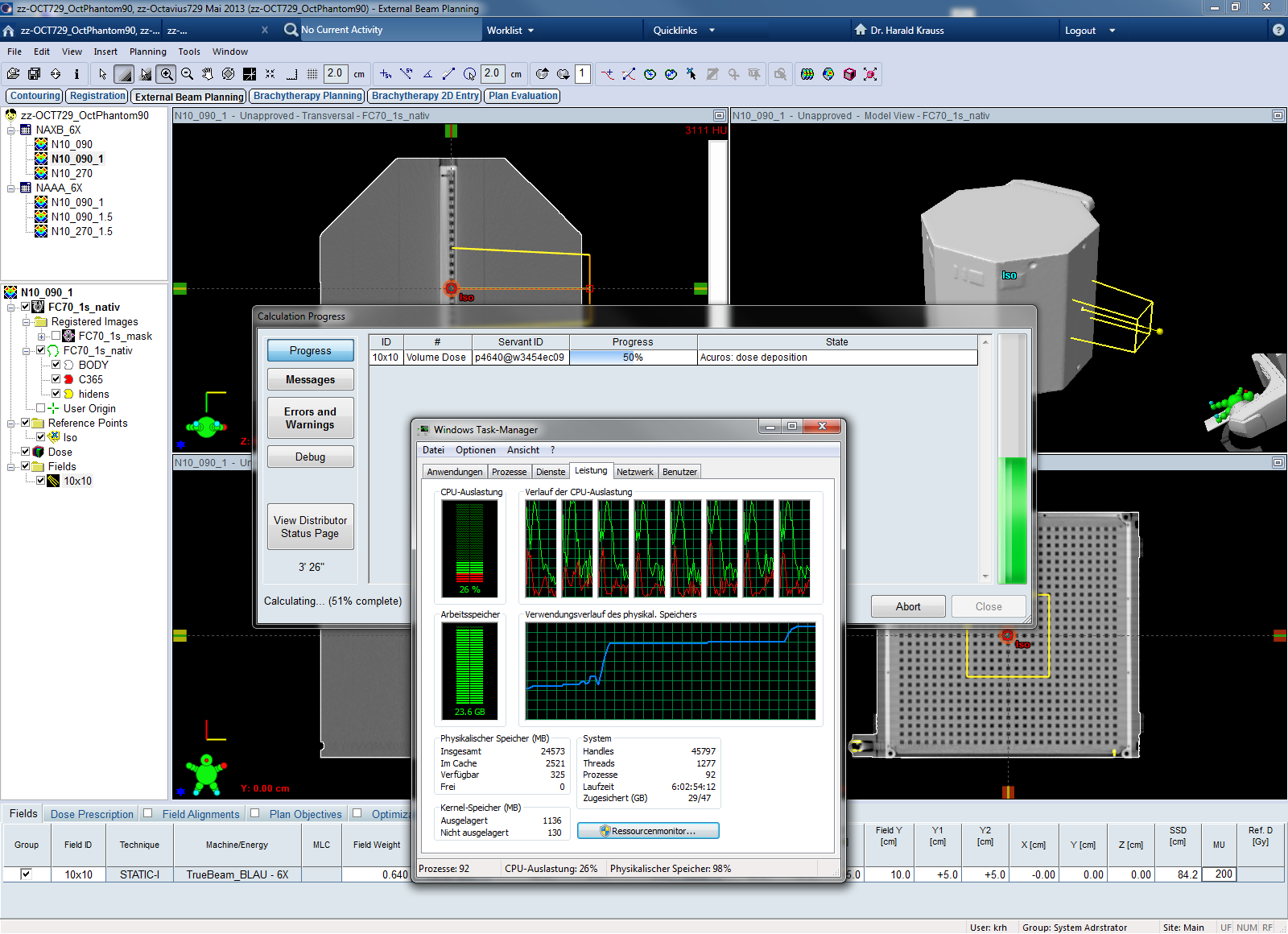
We first looked into the AAA and AXB dose calculations alone, without performing any measurements. The array was in the 90° orientation and the KFJ structure set "native" was used. Only the 6 MV energy was used for this planning study. The idea was to get a rough feeling for the algorithm's characteristics (depth dose, profiles) in the presence of the pronounced heterogeneities of the 2D-Array (vetronit - air - vetronit ...).
Two 10 x 10 cm fields at gantry 90° (the beam enters the OD through the front plane) and 270° (with the beam entering from the back) were calculated. Dose at isocenter and mean dose at chamber C365 were compared. Isodoses and depth dose behavior in proximity to the OD's chamber volumes were analysed qualitatively.
Cross-calibration: Static versus Arc Reference
If the verification measurements are not performed in absolute mode but relative to some reference field (cross-calibration), the absolute dose level entirely depends on this reference measurement. When doing a cross-calibration, it is assumed that the TPS is able to calculate these fields correctly. It is a matter of taste whether the actual temperature and pressure are entered into the software, so that the k(user) factor only contains all other corrections (beam quality, daily output deviations of the linac etc.),
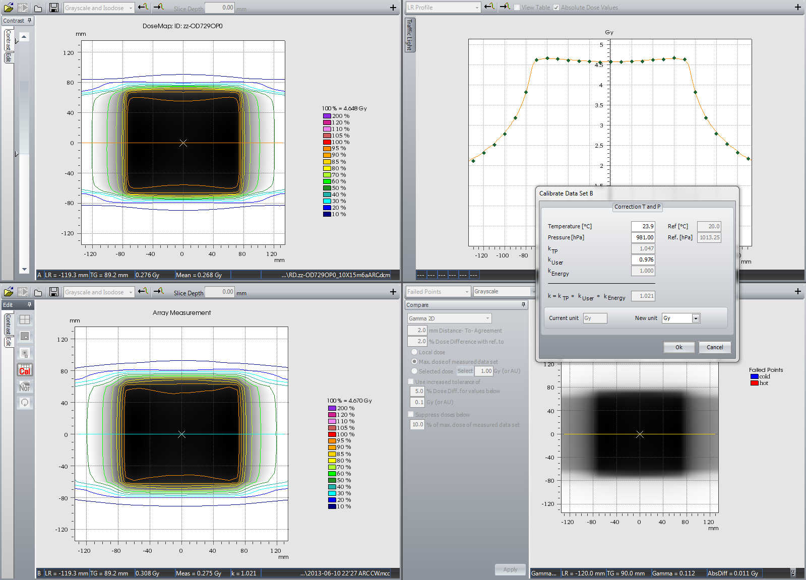
(Fig.3: Determination of the cross-calibration factor k(user) in Verisoft 4.2.)
or T and p are left as standard values (20° C, 1013 mbar), so that k(user) will also contain the air density correction. It really doesn't matter.
In Fig.3, a value equal to 0.976 gives dose agreement at the central chamber. After k(user) has been determined once in a verification session, it is applied to all of the VMAT fields which have the same energy.
We compared two types of reference fields, with the tandem in horizontal orientation. The static reference field is a 15 x 15 cm field with gantry 0°:
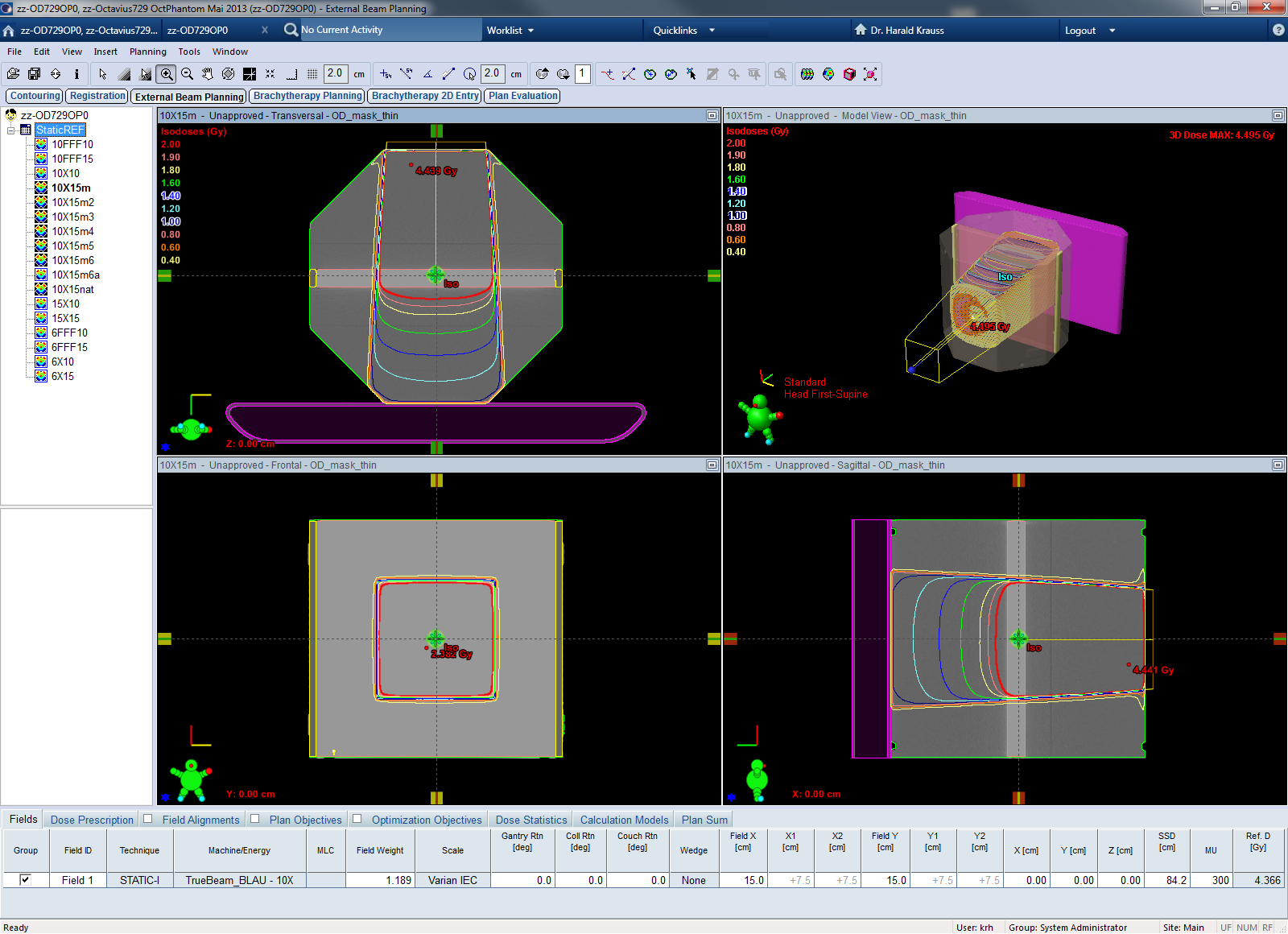
(Fig.4: Static 15x15 reference field on structure set "mask".)
The arc reference field uses a 15 x 15 cm, 360°-arc:
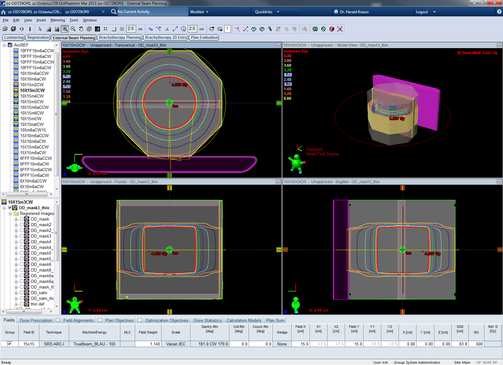
(Fig.5: The 15x15, 360°-arc reference field on structure set "mask".)
The k(user) factors for static and arc reference fields were compared, using only the 10 MV energy. The evaluation was done for all nine structure sets.
Gantry Angle Dependence
To find out which structure set is able to reproduce in Eclipse the measured behavior for oblique beam incidence, we compared calculation and measurement for simple square fields coming from different directions.
The OD was in the horizontal orientation. Static 1-field plans were created with the seven gantry angles 0°, 30°, 60°, 90°, 120°, 150° and 180° using the algorithms AAA, AXM, and AXW.
On the linac, at beam angles 120°, 150° and 180°, the beam is penetrating the couch. To exclude effects from the couch in a first analysis, in Eclipse structure sets without couch were used for dose calculation. For the respective measurements, the OP was rotated by 180° (with the compensating air cavity inside the phantom pointing upwards). The Eclipse beams from 0° to 90° were compared to measurements at the same gantry angles, but Eclipse calculations at 120°, 150° and 180° were compared to measurements at 300°, 330° and 0°, with rotated phantom. This gives the correct beam angle relative to the phantom.
The second analysis was done for the most promising candidate (structure set) from the first analysis. It included the couch in both the measurements and the Eclipse calculations. Dose was calculated for 120° to 180° using a Structure Set with Couch. The couchtop was modeled in Eclipse as "Exact IGRT (thin)" with the default HU setting -300 HU/-1000 HU for Panel Surface/Panel Interior.
The analysis was done for all nine structure sets, 10x10 field size and 6 MV energy.
For each gantry angle, the calibration factor k(user) = k(mean365) which was needed for agreement between Eclipse and measurement at C365 was determined. Ideally, k(user) should not depend on gantry angle at all, but it is quite clear from the design of the array that this will not be acheivable. However, there should not be too large variations in k(user), and upwards peaks of chamber sensitivity at a certain angle should hopefully be compensated by downwards peaks at a different angle. The 90° angle is clearly the biggest challenge, where the beam hits the array from the side.
Clinical Plans
Using selected KFJ structure sets and the PTW structure set, clinical VMAT plans were verified with the OD/OP tandem. Measurements were performed on the TrueBeam. All evaluations were performed with VeriSoft 4.2.