Eclipse 8.6 introduced couch modelling (see also the page on the basics).
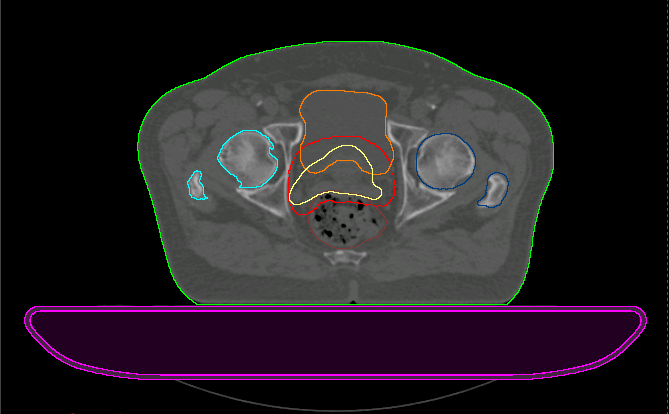
The standard procedure in our department is to insert the synthetic couch model to a patient's 3D-model whenever a treatment plan might be created that has fields going through the couchtop (see some restrictions on the right). Couch models are mostly added for head & neck, prostate, and lung patients.
The dosimetric impact can easily be assessed by comparing plans with and without couch model. Special attention shall be paid to the two movable carbon rails, which are part of Varian's Exact Couchtop.
The Flat Panel
Our machines have the Exact Couchtop installed which consists of a flat carbon panel and two movable carbon rails. If a beam enters perpendicularly (Gantry 180°) and the default HU values of Eclipse's couch model are left unaltered, the water equivalent depth of the flat panel is about 5mm:
This is consistent with our own measurements.
The Rails
The two carbon rails are tilted inwards by 11.2°. This has been verified on our real machines with the help of a clinometer.
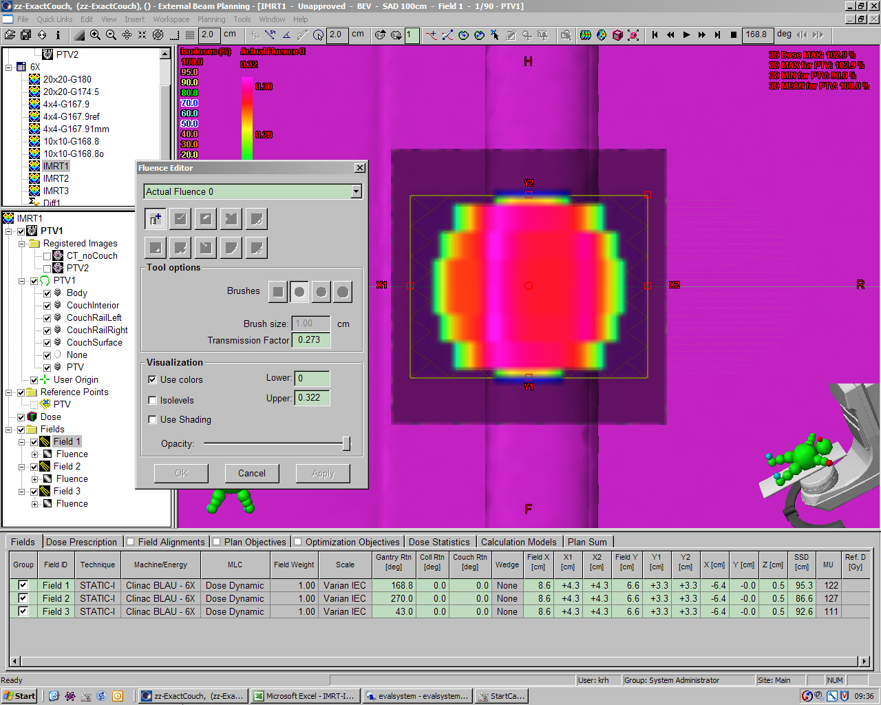
One can easily find the "worst case" beam setup which gives the maximum dosimetric effect: to acheive "maximum dose error" (let's say the left rail is in the beam where it shouldn't be), the Gantry angle has to be at 168.8° and the Couch moved laterally until it is aligned with the beam.
For this setup, two plans were created which deliver a fixed number of MU with a single 6MV, 10x10 field. In one plan, the couchtop and the rail is in the beam. In the other plan, the "patient" is floating in free space*. The plans were calculated with the Anisotropic Analytical Algorithm (AAA version 8.6.14).
In the following image, the plan without the couch is substracted from the plan with the couch. The maximum dose difference for this "worst case" setup is about 0.28Gy which is equivalent to a maximum (local) dose error of 28%:
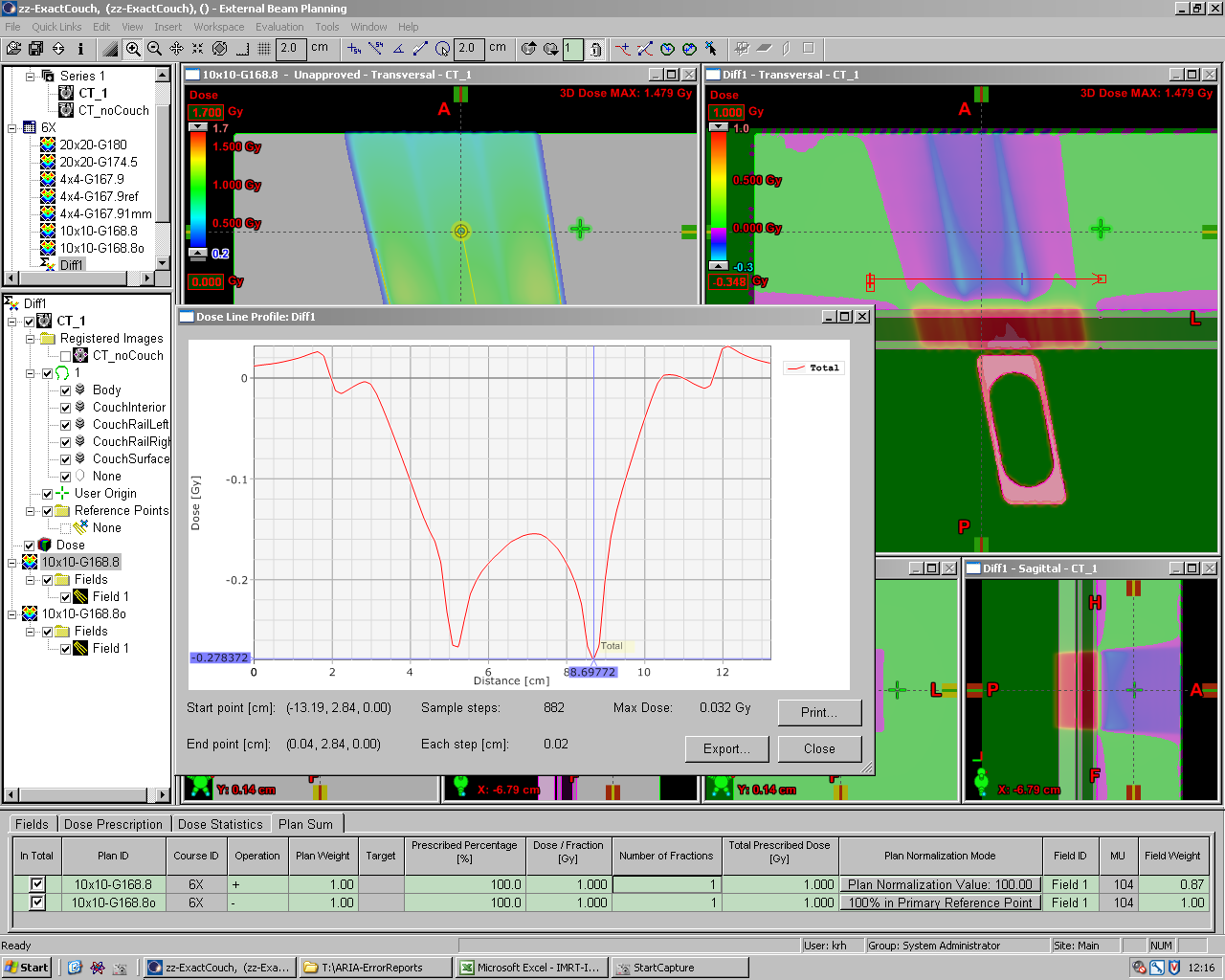
(click to enlarge)
In terms of water equivalent depth, the local difference is between 5mm (flat panel alone) and more than 10cm(!) of water in the shadow of the rail's side wall:

(click to enlarge)
Two notes:
- In order to see isodoses inside the couch structures, the box which limits the isodose display has to be expanded manually, using the
 icon. Simply expanding the isodose area with the
  icon will not work. This would only expand isodose display up to the Body outline. But the Couch structures are outside the Body structure.
 - The source surface distance (SSD) does NOT include the Couch structures. In the image, the SSD is 95.5cm in both plans. This is the distance from focus to the Body surface.
Dose display has nothing to do with dose calculation. The absorption of the Couch structures are always taken into account, whether isodoses are displayed or not. If you are not interested in seeing isodoses inside the Couch, you do not have to do anything.
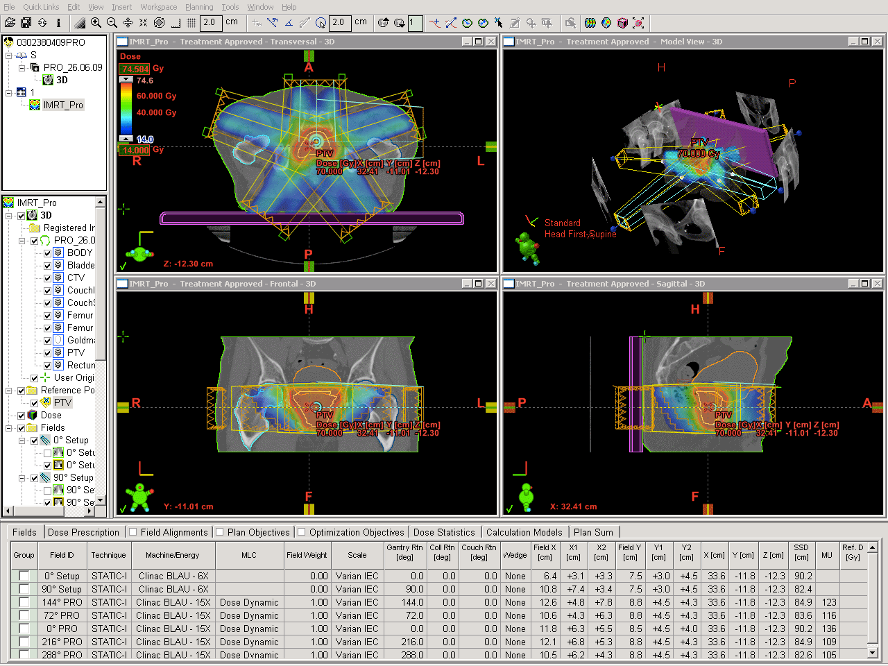
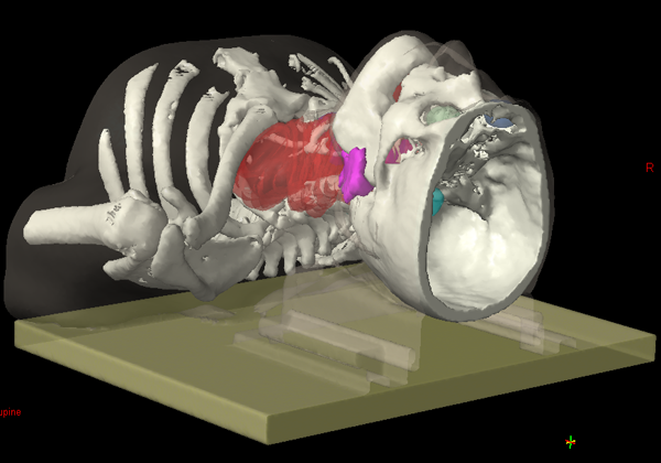
The Exact Couchtop and RapidArc
If the Exact couch with rails is installed on the treatment machine, dose planning should include the rails., which is done automatically during optimization and during dose calculation. Of course, this only works if the rails are not deleted manually!
During a full 360° RapidArc treatment, the rails are in the beam twice:
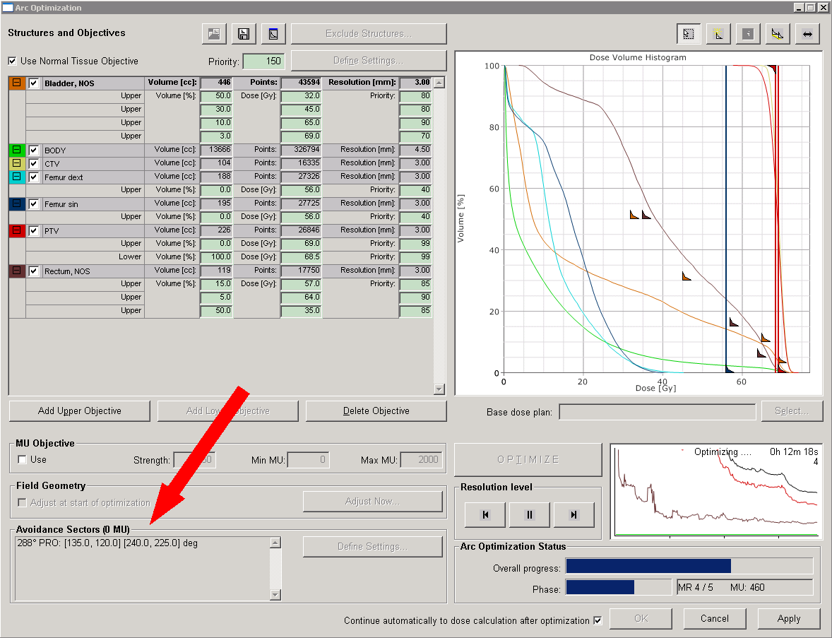
If you still feel uncomfortable beaming through the rails, you can use Eclipse's feature of avoidance sectors and reduce fluence delivery to zero while the rails are in the beam ...
The MLC leaves are not displayed, only the MLC aperture and the jaws, for better clarity.
If the movies appear out of sync, reload the page. If you are interested in a full-quality stand-alone movies, you may download the AVIs here and here. There is also a version of the first movie with MLC.
What is the potential dose error during RapidArc?
Let's assume the rails were at the OUT position during planning but at the IN position during treatment.
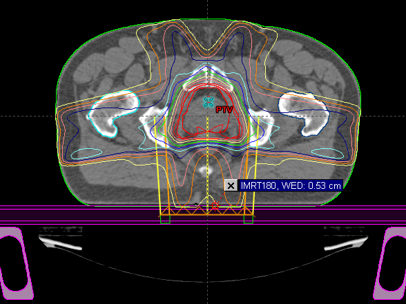
The optimized plan (45A = "A") will assume the rails OUT. A copy of this plan, (45B = "B"), was recalculated without reoptimization on a structure set with the rails IN. The plan B therefore corresponds to the wrong treatment setup. The difference of the two plans, B-A, was calculated. The dose profile through the difference plan starts behind the rectum and crosses the PTV and the bladder:
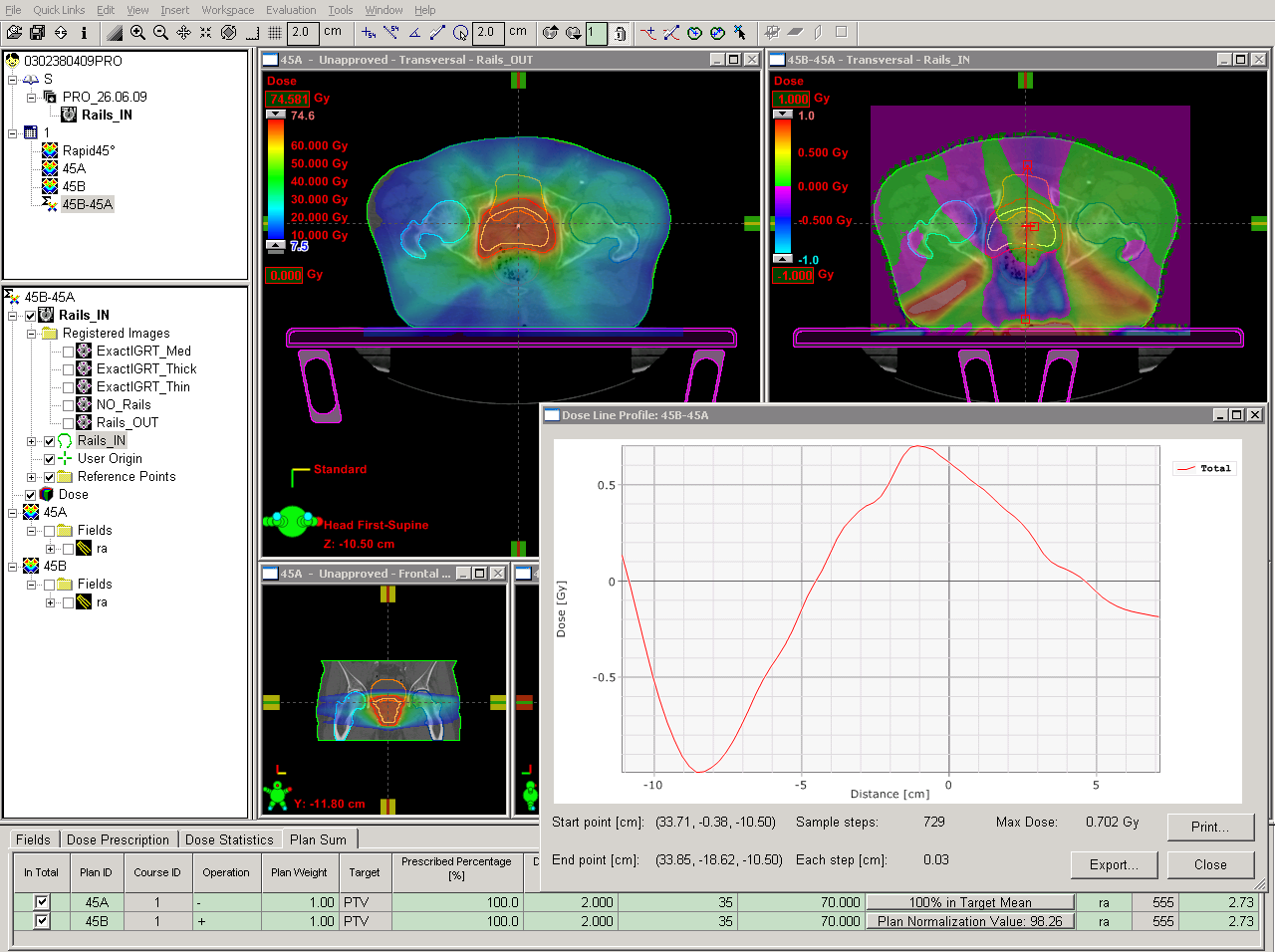
(click to enlarge)
Negative values (in the rectum) are under-, positive values (in the PTV) are overdosed. The amount of overdosage (up to 0.7Gy) has to be seen in relation to the prescribed dose of 70Gy. This gives a maximum error inside the PTV of about 1%, if the rails are in the wrong position during the treatment.
The negligible impact can also be seen in the DVH:
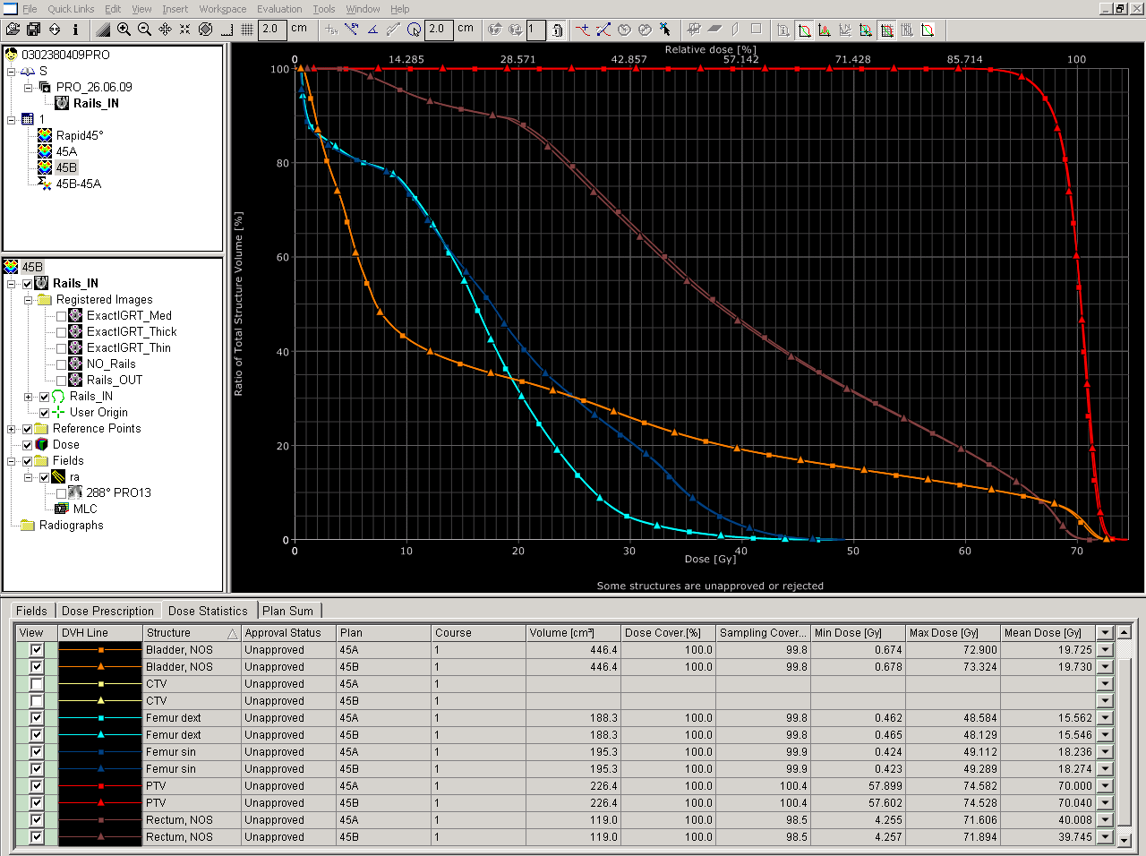
(click to enlarge)
Except for a slightly better sparing of the rectum, the total effect is small. One could even say that the plan with the wrong rails is the better plan (maybe we should treat all prostate patients this way?).
Conclusions
The rails should not be ignored for fixed beam techniques like IMRT, especially if beams pass through them and the number of fields is small.
During RapidArc, since there are no fixed beam angles, the percentage of MU where the rails are in the beam is generally much lower than during fixed-angle IMRT. For a typical 360° RapidArc prostate treatment with 15MV photons, the effect of wrong rail positioning is therefore very small.
This is a clear advantage of RapidArc over fixed-angle IMRT.
*In German, there is a technical device called Siemens Lufthaken, which helps stabilize free-floating structures from being attracted gravitationally.