

Material and Methods
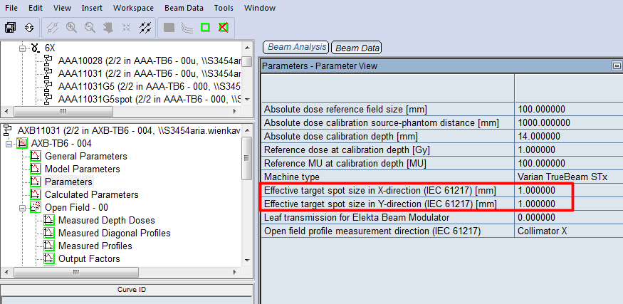
In the beam models AAA11031G5 and AXB11031G5 described recently, the target spot size parameters in X and Y direction, SpotX and SpotY, had been set to a "guessed" value of 1 mm. We will use film dosimetry to optimize the spot sizes in Eclipse.
As described in the article of Torsti (Torsti et al. 2013), one has to decide1 whether spot size shall be optimized for open fields (where the field aperture is defined by the jaws alone), or MLC fields (where the MLC shapes the field). In MLC fields jaws are present, but only provide additional shielding.
We perfer to optimize to MLC fields ("MLCspot") instead of jaw-defined fields ("JAWspot"), because it is clinically more relevant: practically all fields have an MLC2.
We will evaluate three small test fields:
- "1x1JAW": a 1 x 1 cm field with the field defined by the jaws (MLC retracted),
- "1x1MLC": a 1 x 1 cm field defined by the HD120-MLC (jaws set to 2 x 2 cm),
- "05x05MLC": a 0.5 x 0.5 cm field defined by the HD120-MLC (jaws set to 2 x 2 cm).
The spot size parameters in the Eclipse beam models (new models AAA11031G5spot and AXB11031G5spot) will be tweaked until good agreement is reached between calculation and measurement for both small field absolute dosimetry and profile shape of small fields.
Field and Phantom Setup
During all irradiations (film calibration, test field delivery) the EBT3 film is placed inside a "topless" Octavius phantom:
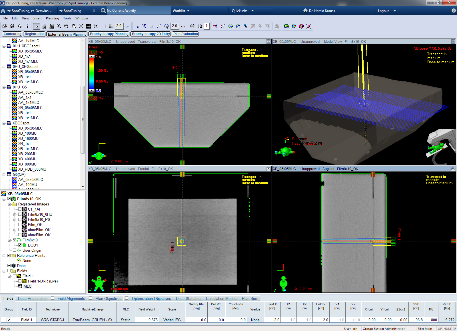
The lower part is the 12 cm thick top of the Octavius phantom (turned upside down). The upper part is the 3.2 cm thick plate of the OP which normally comes on top of the 2D-Array. With their tongue and grooves, these two phantom parts fit together nicely. Sandwiched between the two is the 8 x 10" film, which was also present during the CT scan of the phantom (the coronar Eclipse view actually shows the film plane).
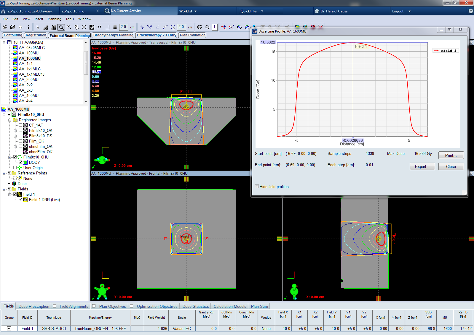
The Body outline was generated automatically (-350 HU threshold). Field isocenter was placed in the film plane. A calculation grid size of 1 mm was used for all calculations. Dose reporting mode for all Acuros XB calculations was Dose to Medium (D2M). Calculated dose planes were exported with a size of 10 x 10 cm and 512 x 512 px. This gives a spatial resolution of 0.2 mm. All test field calculations were performed with fixed 800 MU. The absolute dose distribution in the film plane was evaluated with PTW VeriSoft 6.0.
Acuros XB calculations are more sensitive to small HU fluctuations in the CT images than AAA calculations. The sceenshots show the calculation on the homogeneous phantom with 0 HU in the upper image, the "native" calculation in the lower image. The %difference image is more homogeneous for the AAA calculation. To rule out any density effects which might disturb the comparison of AAA and AXB, all calculations were therefore done on a structure set where the Body outline was masked with 0 HU (material water).
Starting Point: SpotX = SpotY = 1 mm
Before doing the measurements, we want to compare some Eclipse calculations. In the following, both AAA and AXB use the same spot size: SpotX = SpotY = 1 mm. We also keep in mind that both beam models, AAA11031G5 and AXB11031G5, were generated with exactly the same input data.
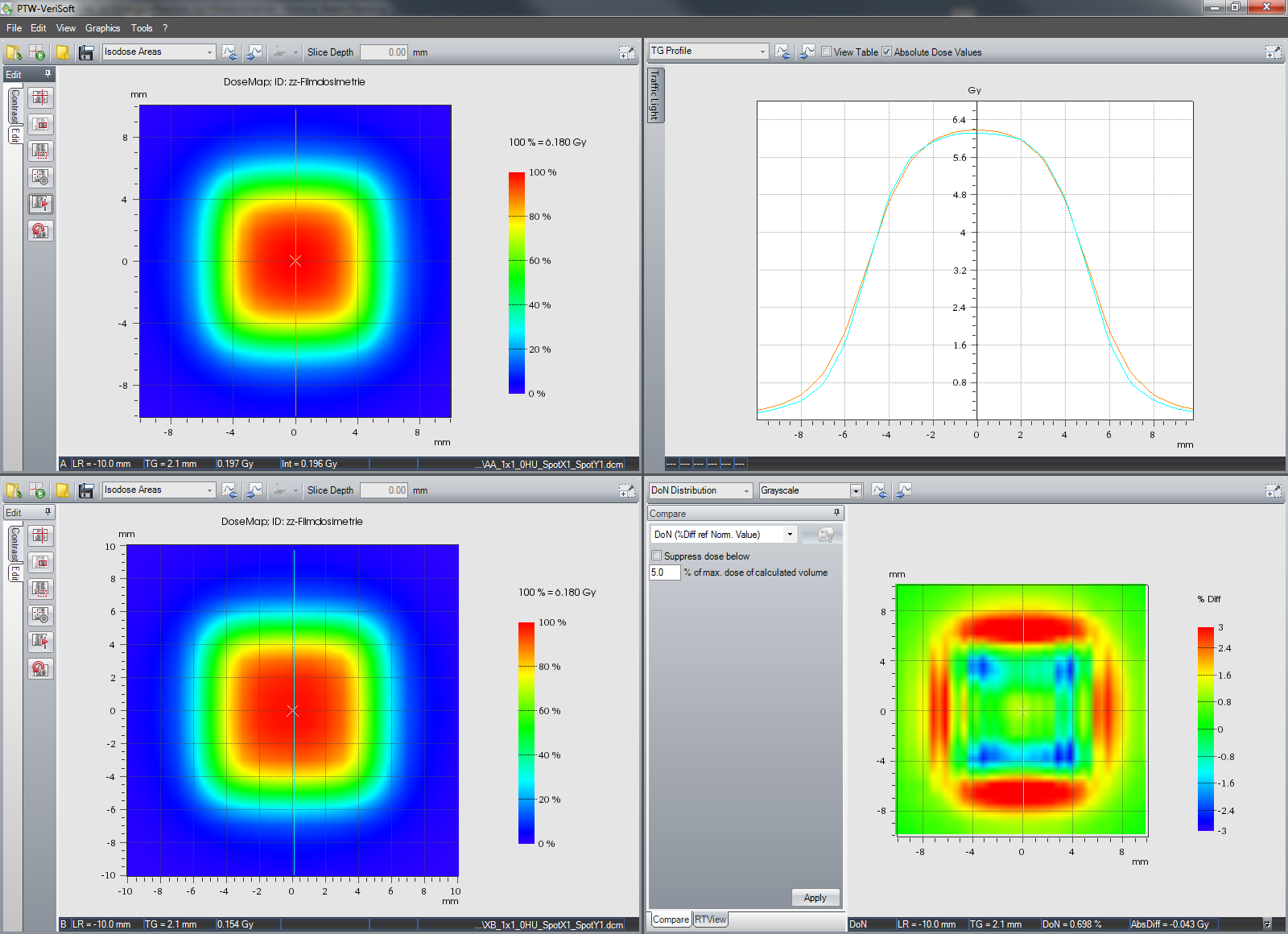
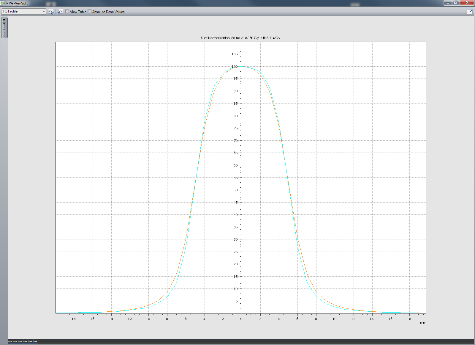
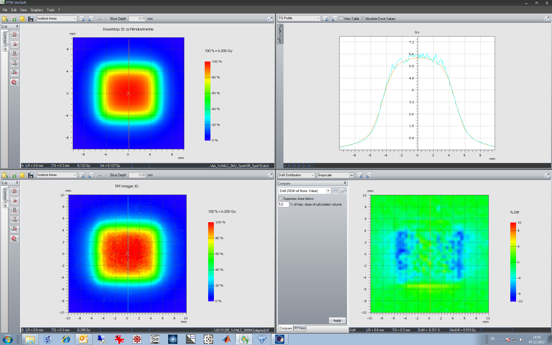
- The 1x1JAW field, calculated with AAA (top left) and AXB (bottom left) is shown. The inplane profiles are in the upper right subplot. AAA dose at isocenter is slightly higher (6.180 Gy for AAA versus 6.114 Gy for AXB, 0.58% difference). After renormalization to CAX, one sees that AXB penumbras are slightly smaller than AAA penumbras. Inplane the difference is more pronounced than crossplane (AAA is the brown, AXB the cyan curve).
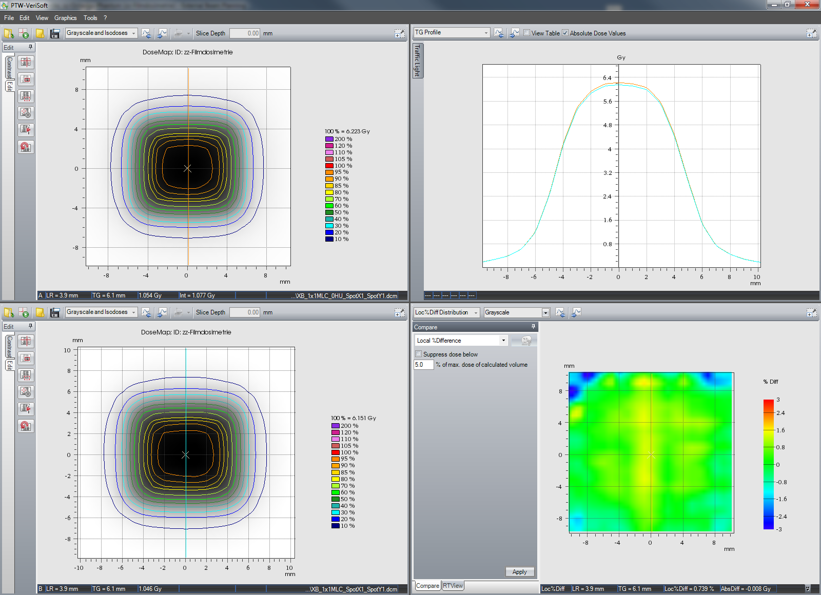
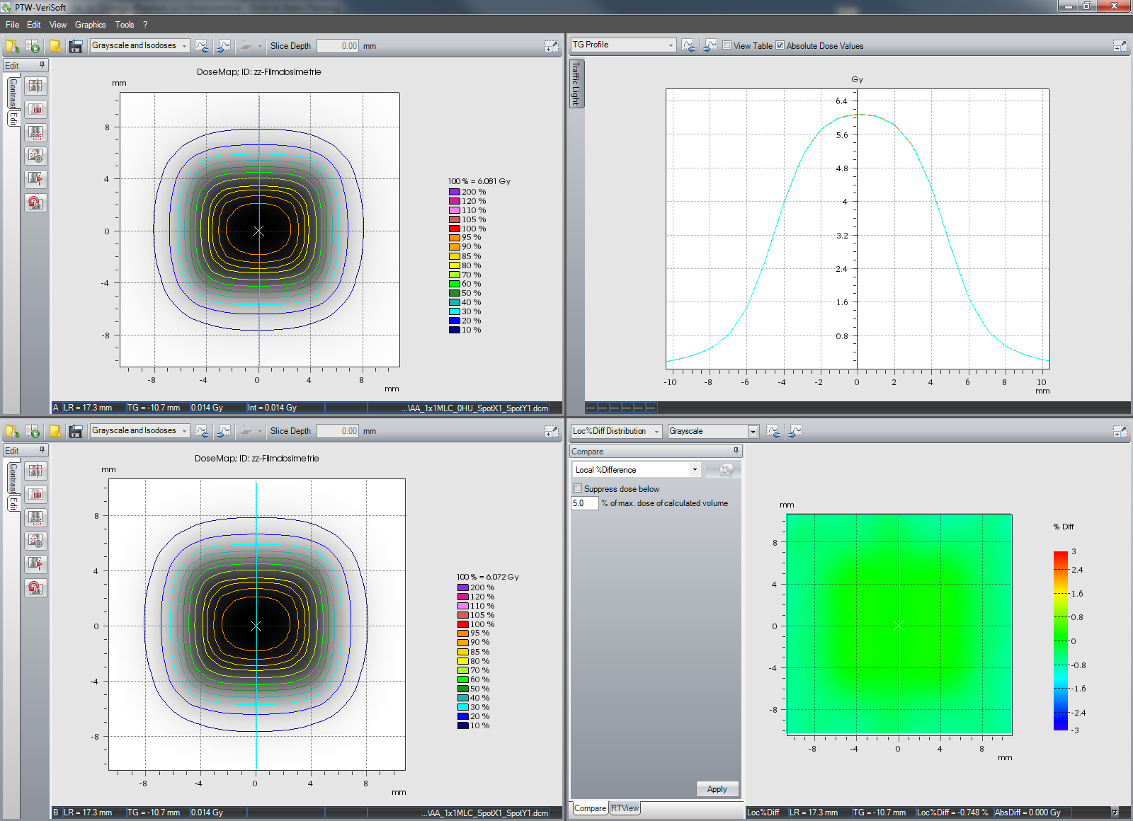
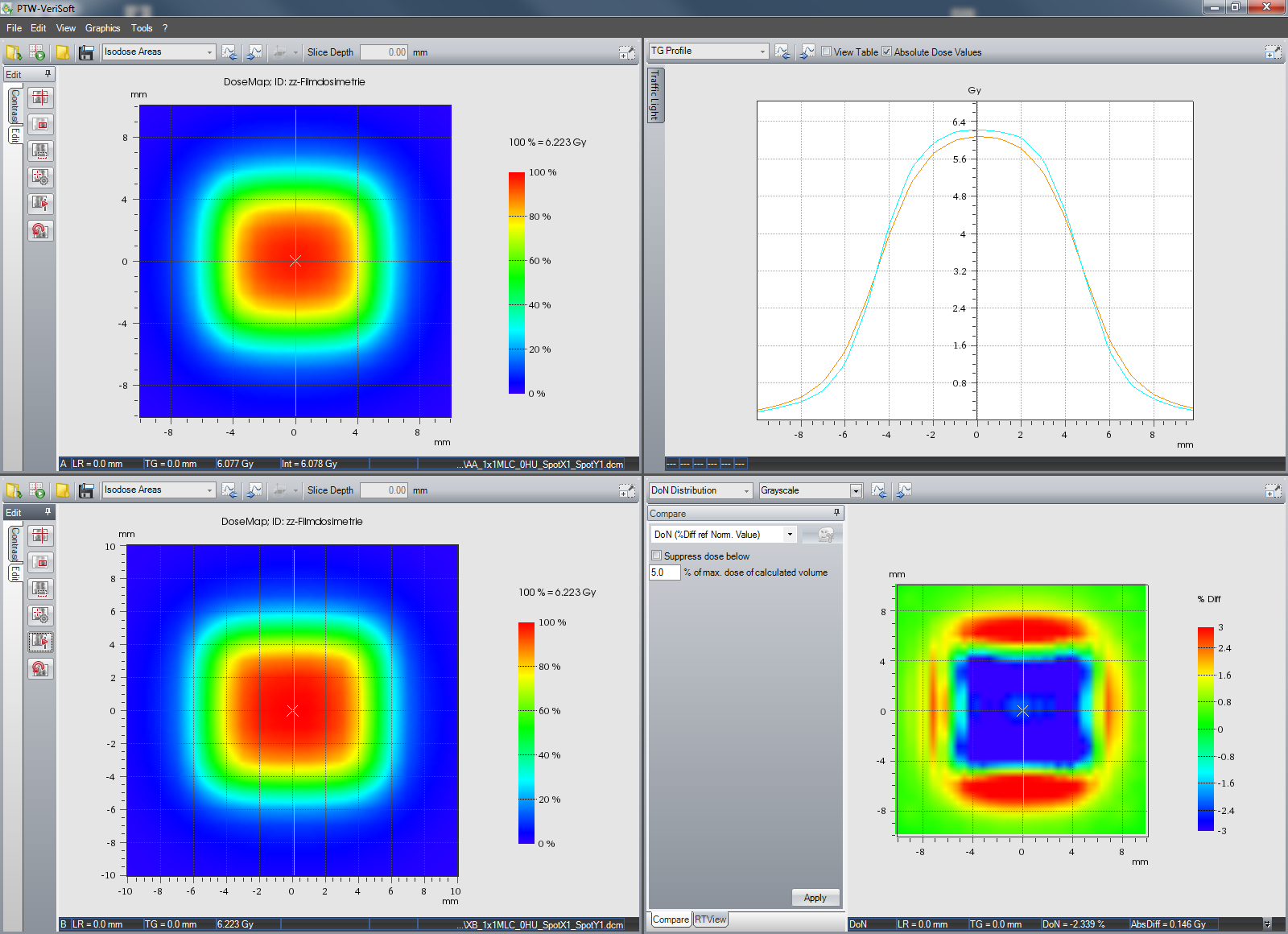
- For the 1x1MLC field with jaws set to 2 x 2 cm, the dose difference between AAA and AXB is larger: now AXB dose (6.223 Gy) is higher than AAA dose (6.081 Gy, 2.3% difference). Again AXB produces sharper penumbras than AAA: inplane the difference is bigger, crossplane the penumbras are nearly the same.
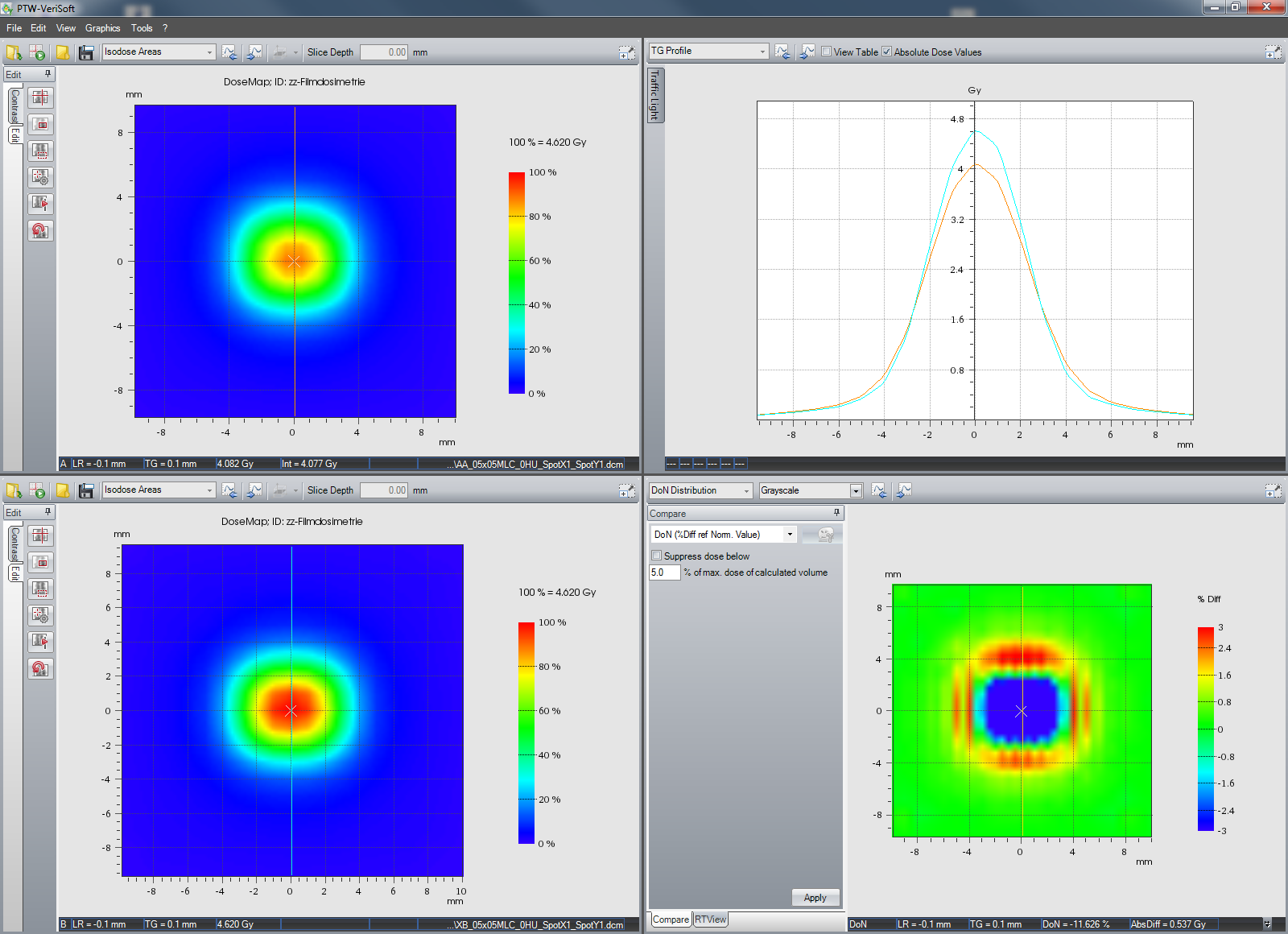
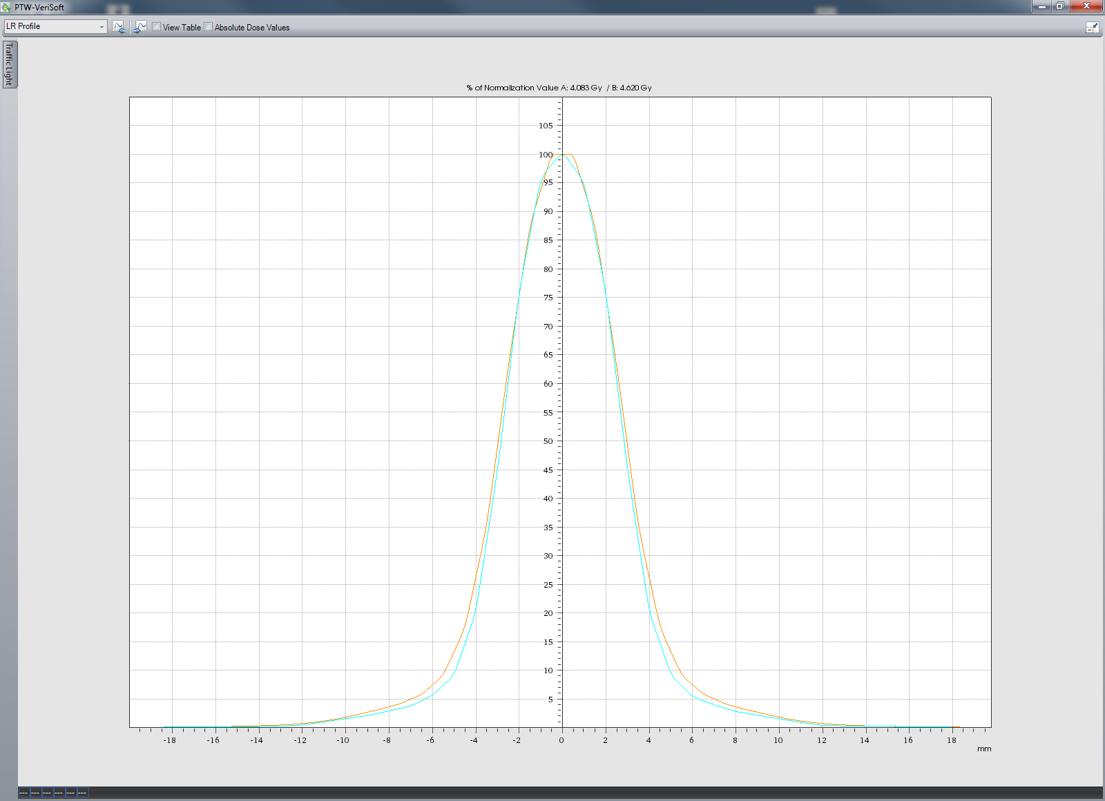
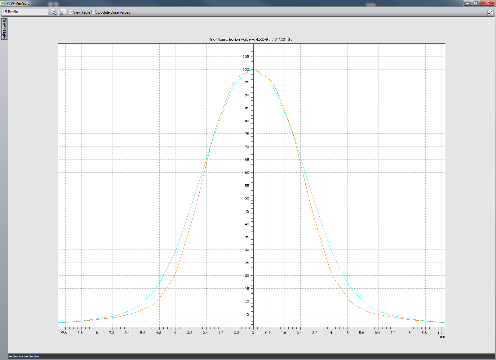
- The smallest of our three test fields is the 05x05MLC field defined by the HD120-MLC, with jaws set to 2 x 2 cm. Again, AXB dose is higher (4.620 Gy) than AAA dose (4.083 Gy). Now the difference is about 13%. The normalized curves in the inplane (perpendicular to the leaves) and crossplane (along the leaves) direction are brown for AAA and cyan for AXB.
So far the comparison between the two initial beam models AAA11031G5 and AXB11031G5 with SpotX = SpotY = 1 mm. Film analysis will tell which model is closer to reality and in which direction spot sizes have to be tweaked to improve agreement.
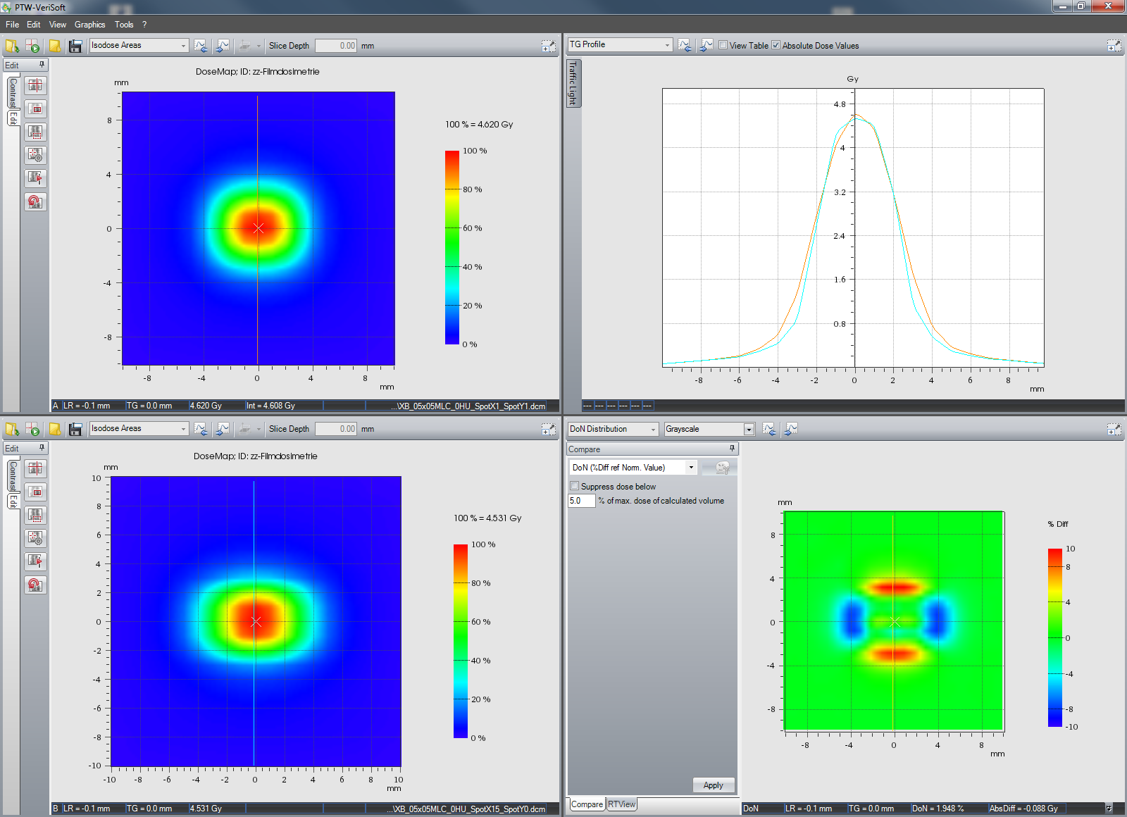
What change in isodoses can we expect if we change the spot size? In this graph, a comparison of two AXB calculations of the 05x05MLC field is shown, with different spot sizes. Top left is the known SpotX = SpotY = 1 mm (brown curve), bottom left is the modified SpotX = 1.5 mm, SpotY = 0 mm (cyan curve). As expected, due to the increased spot size in X direction, the crossplane profile gets broader, whereas the dose fall-off in inplane direction is now steeper. Absolute dose in this case stays more or less the same.
Film Measurements
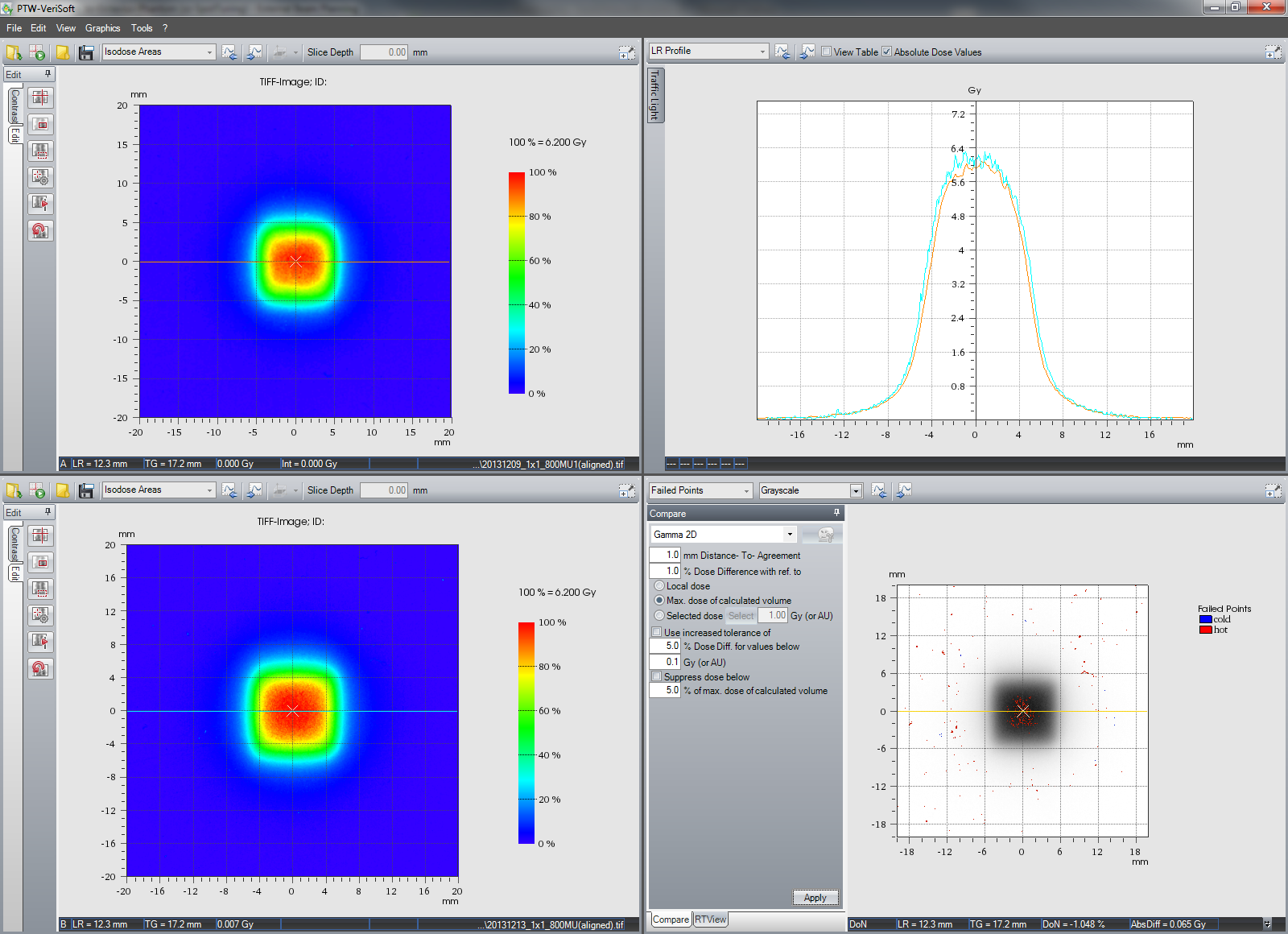
The 1x1JAW field calculated with AAA and SpotX = SpotY = 1 mm (upper left) is compared to the film measurement (lower left).
Inplane the calculated dose fall-off is a little steeper, whereas crossplane the measured dose fall-off is steeper. We could try to correct this in the model by reducing JawSpotX and increasing JawSpotY. However, the specification for jaw position accuracy, even on the TrueBeam, is only 1 mm per jaw. Here is a comparison of two film measurements of the same 1x1JAW field, from two different TrueBeams. The 1x1 field on one machine is larger in both inplane and crossplane direction, but still within specs. Varian considers the jaw as backup shielding device, and not as the primary field forming device (which is the MLC). This has to be kept in mind.
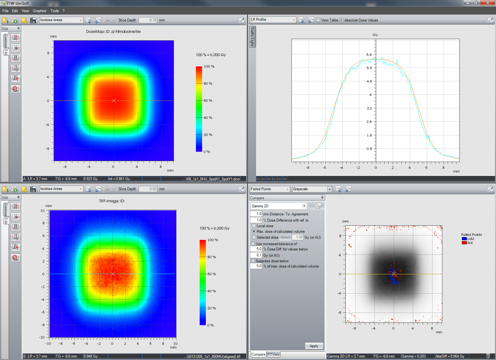
The same holds for the comparison of AXB and Film:
To improve agreement, JawSpotY would have to be increased a little. Crossplane, the agreement is better than with AAA, and seems quite acceptable.
Absolute dose agreement for the 1x1JAW field is satisfactory with both algorithms (considering the high noise level in the film, which is caused by our very limited experience with film dosimetry).
As already mentioned, we want to focus on the MLCspot. The 1x1MLC field is evaluated next.
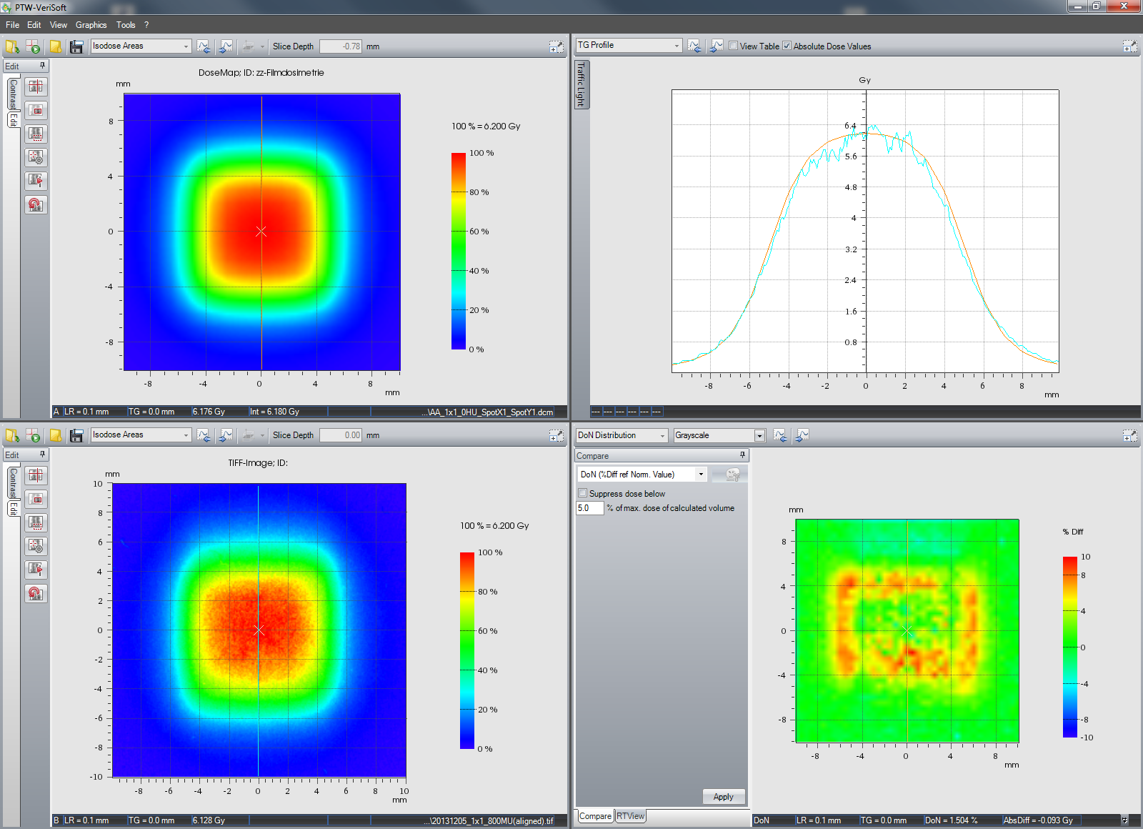
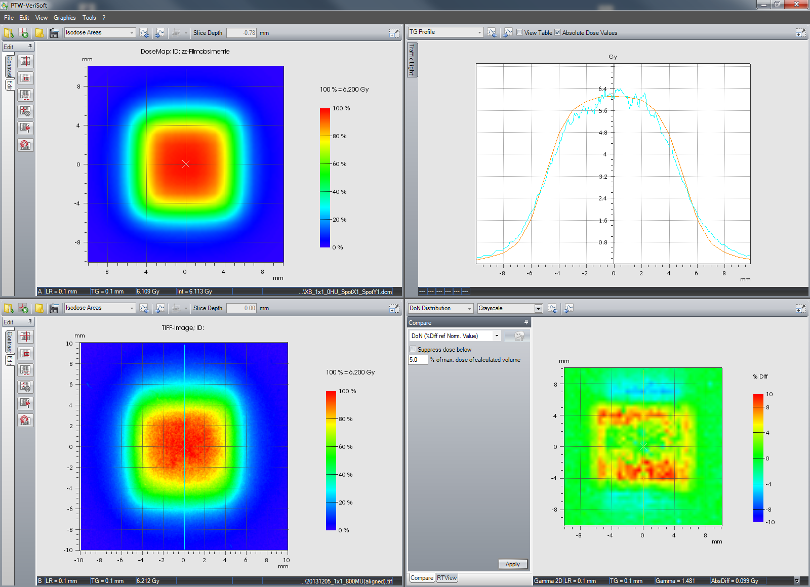
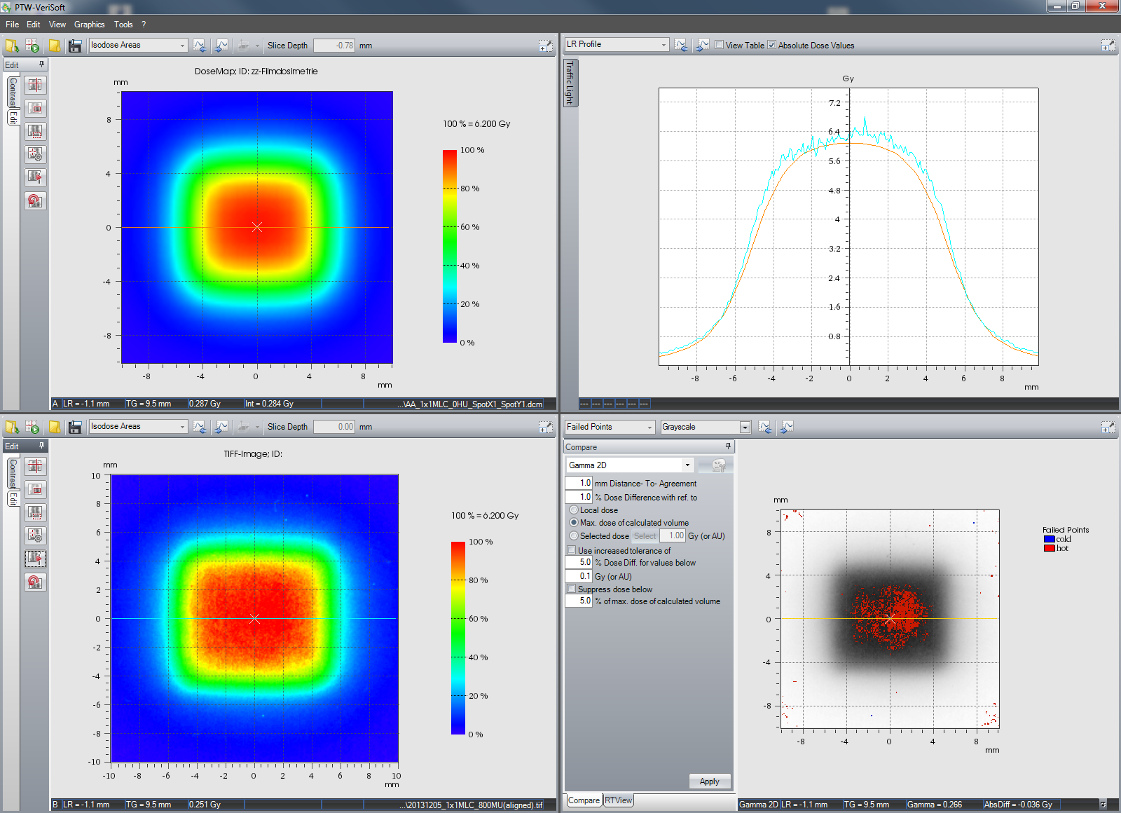
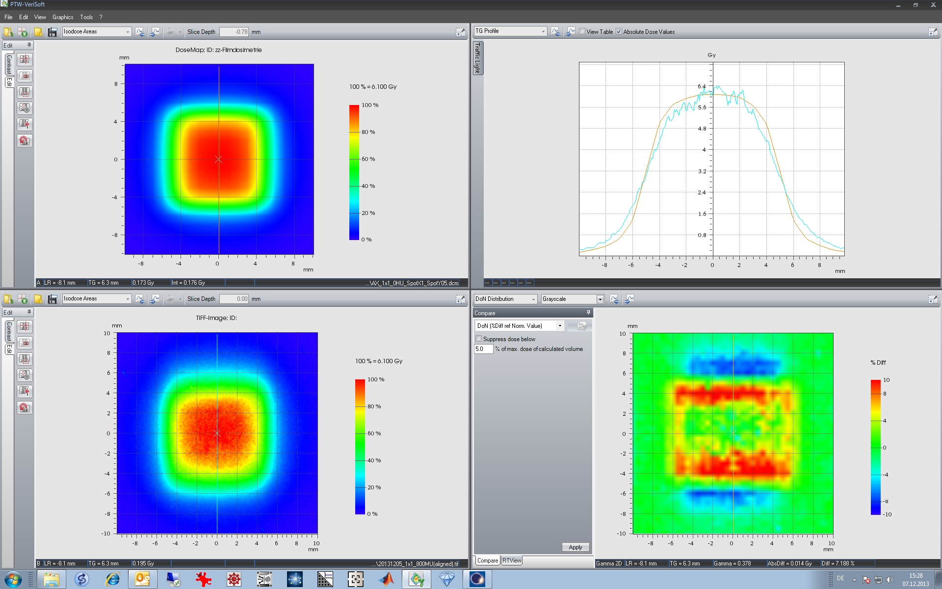
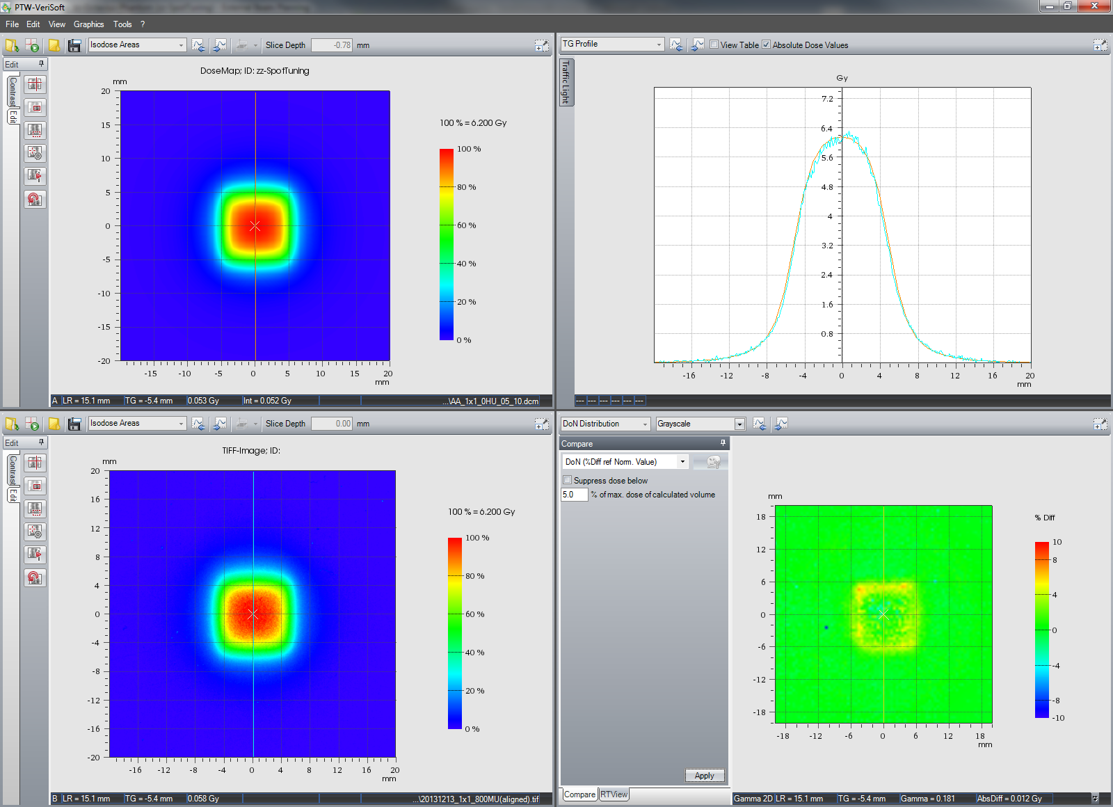
First, the AAA calculation with SpotX = SpotY = 1 mm (upper left) is compared to the film measurement (lower left):
Both inplane and crossplane, measured dose fall-off is clearly steeper. Measured dose at isocenter is higher than AAA calculated dose. This would call for a reduction in both MLCspotX and MLCspotY in the AAA model.
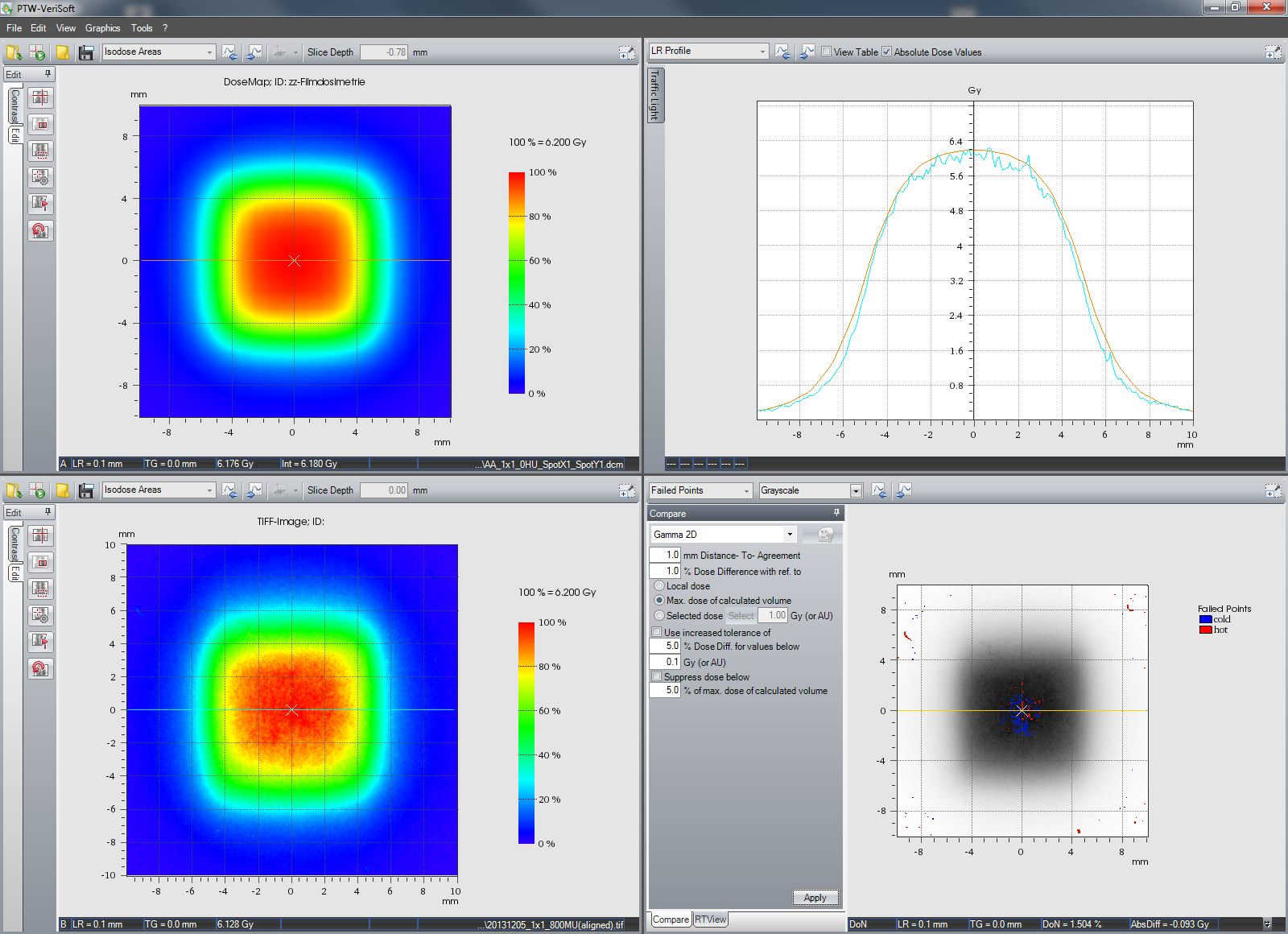
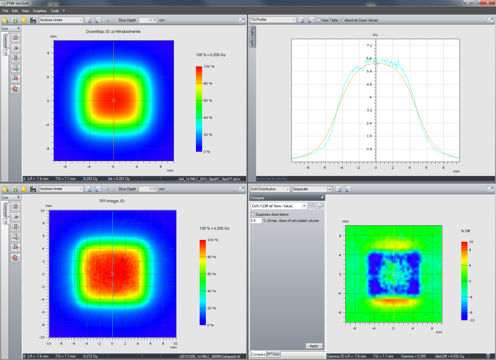
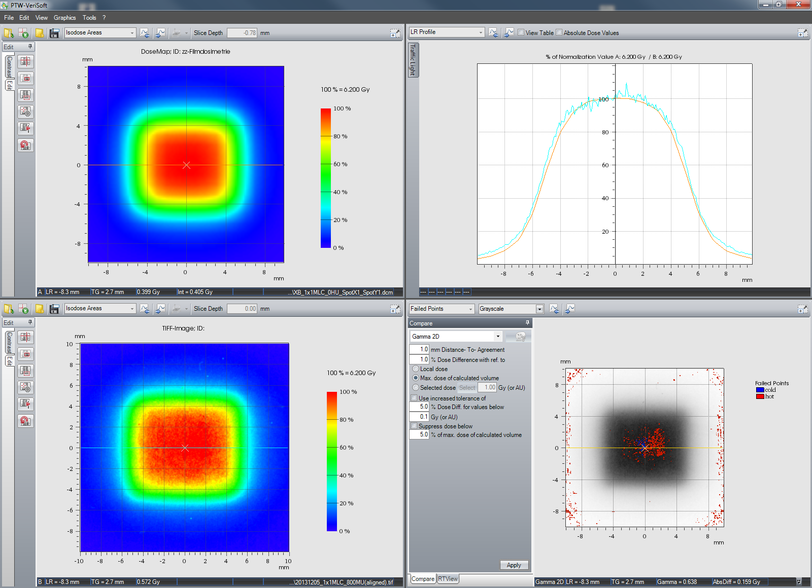
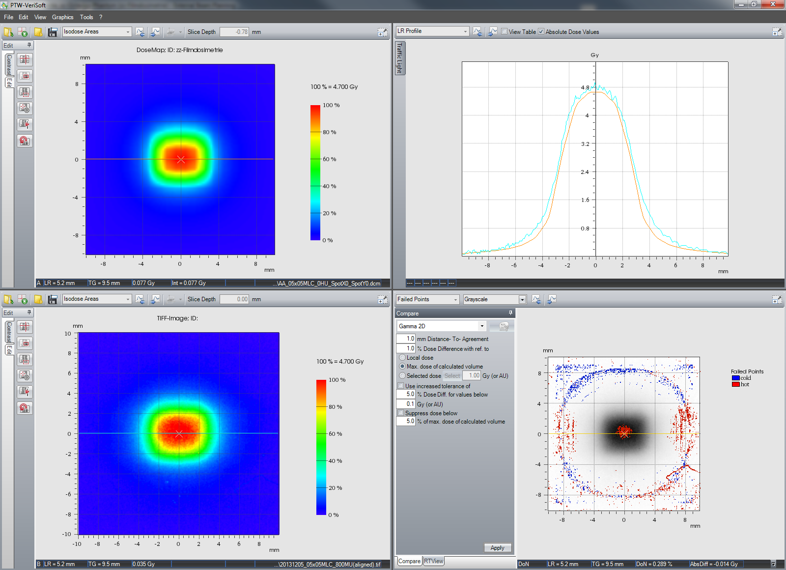
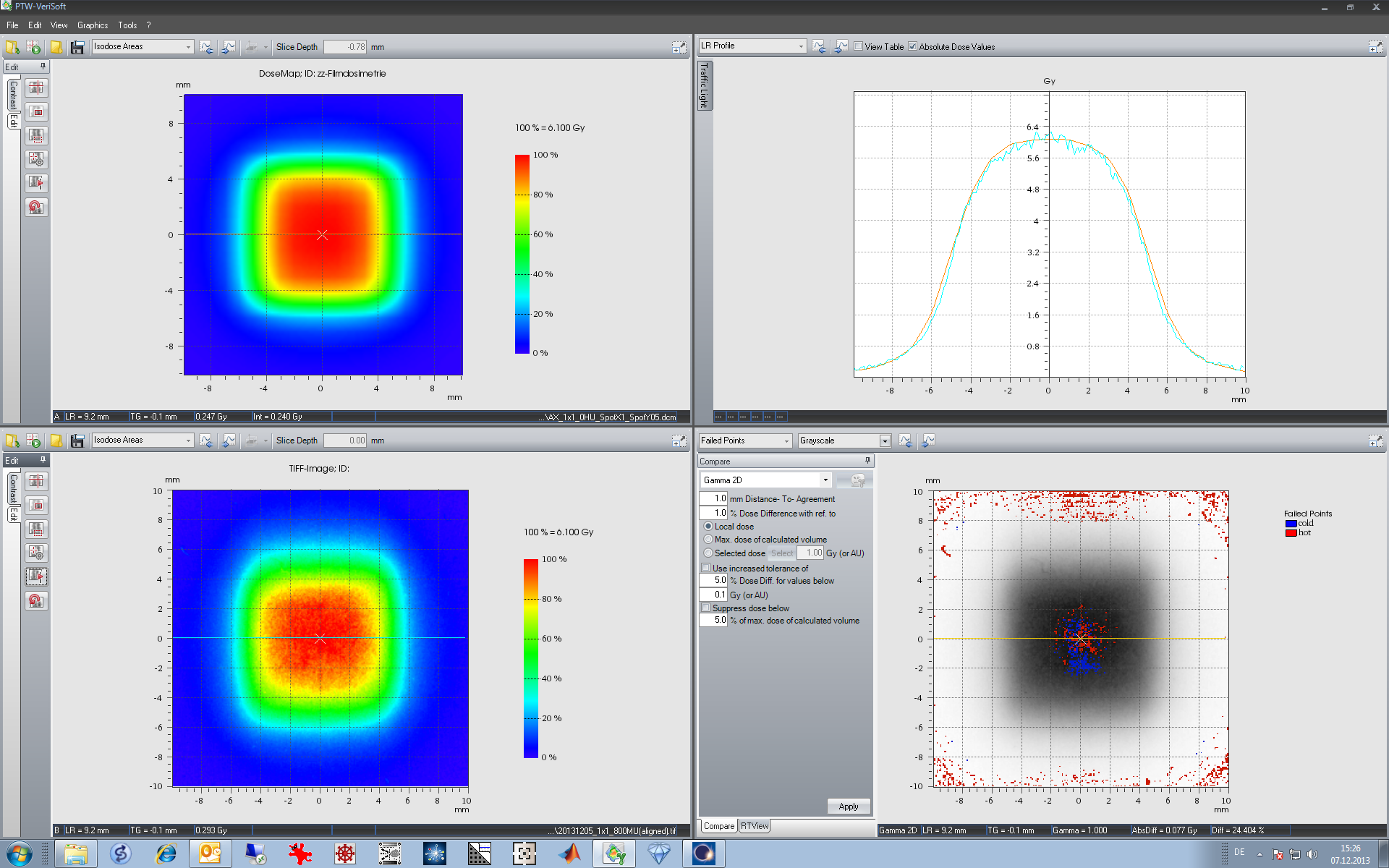
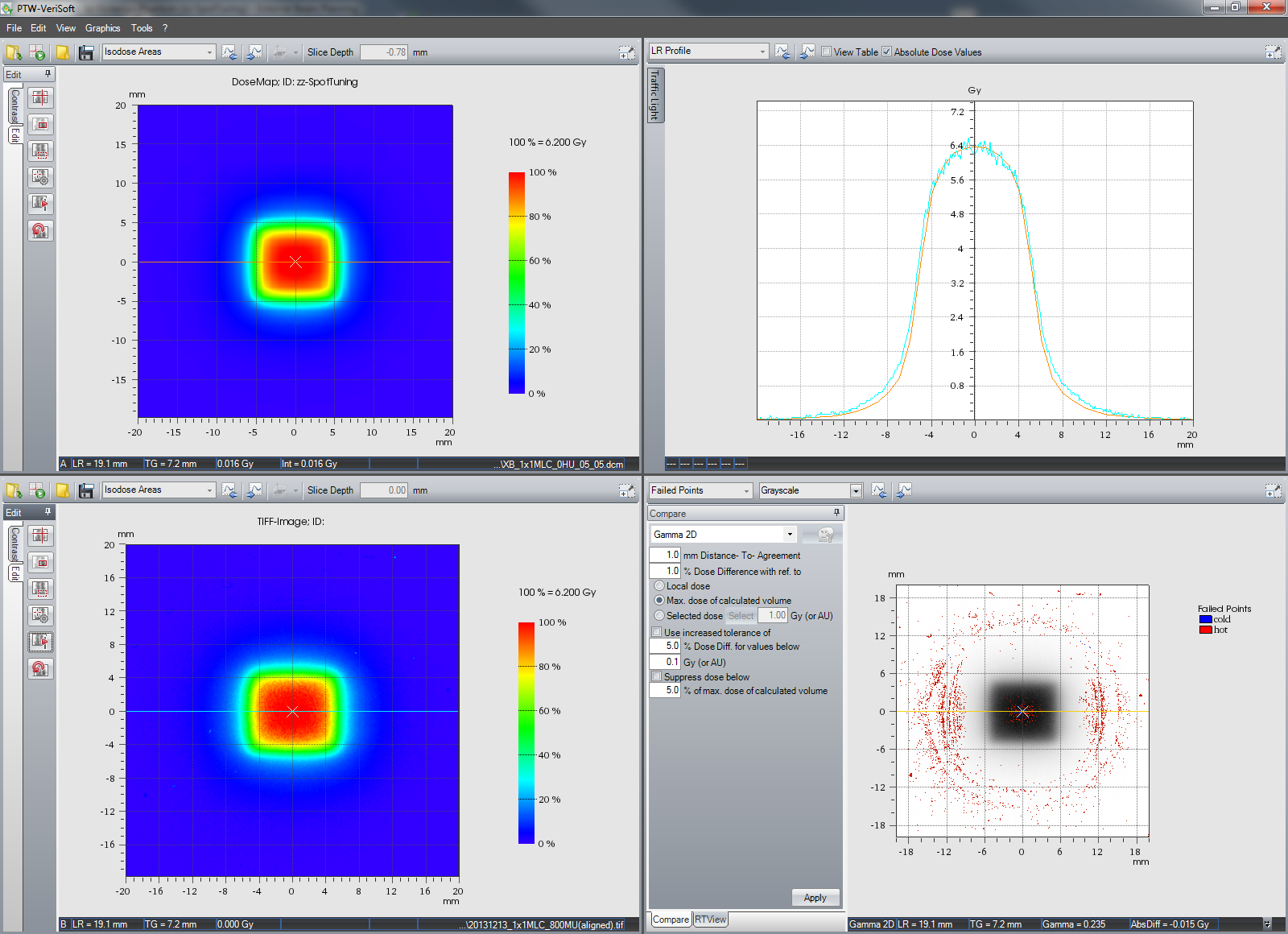
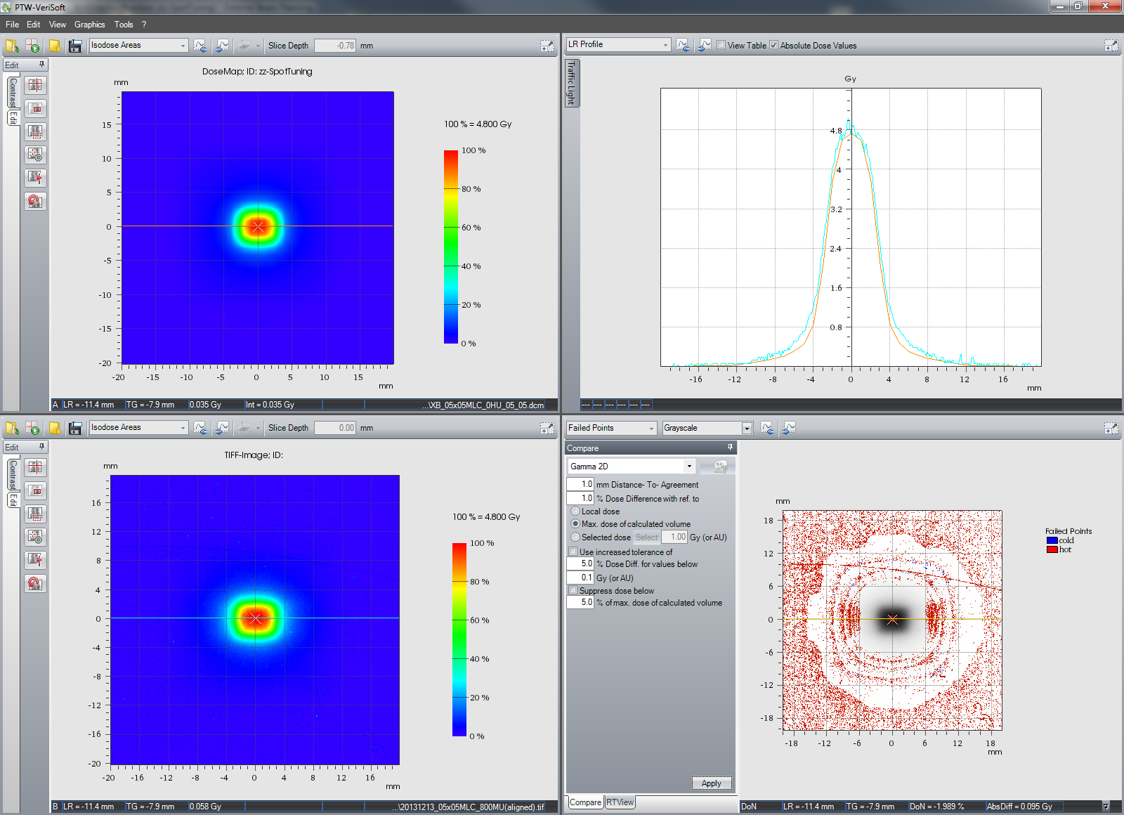
Now the AXB calculation with SpotX = SpotY = 1 mm. Inplane agreement is quite good,
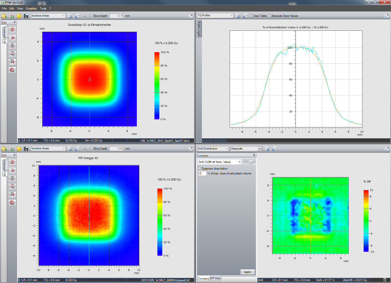
crossplane (in leaf direction) the measured field seems a little wider. Steepness of dose fall-off seems OK. We could reduce MLCspotX a little, just to see what happens.
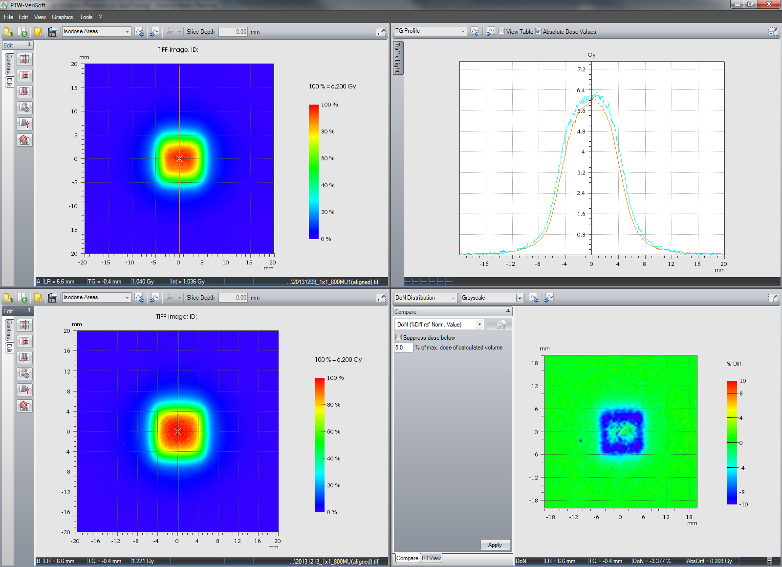
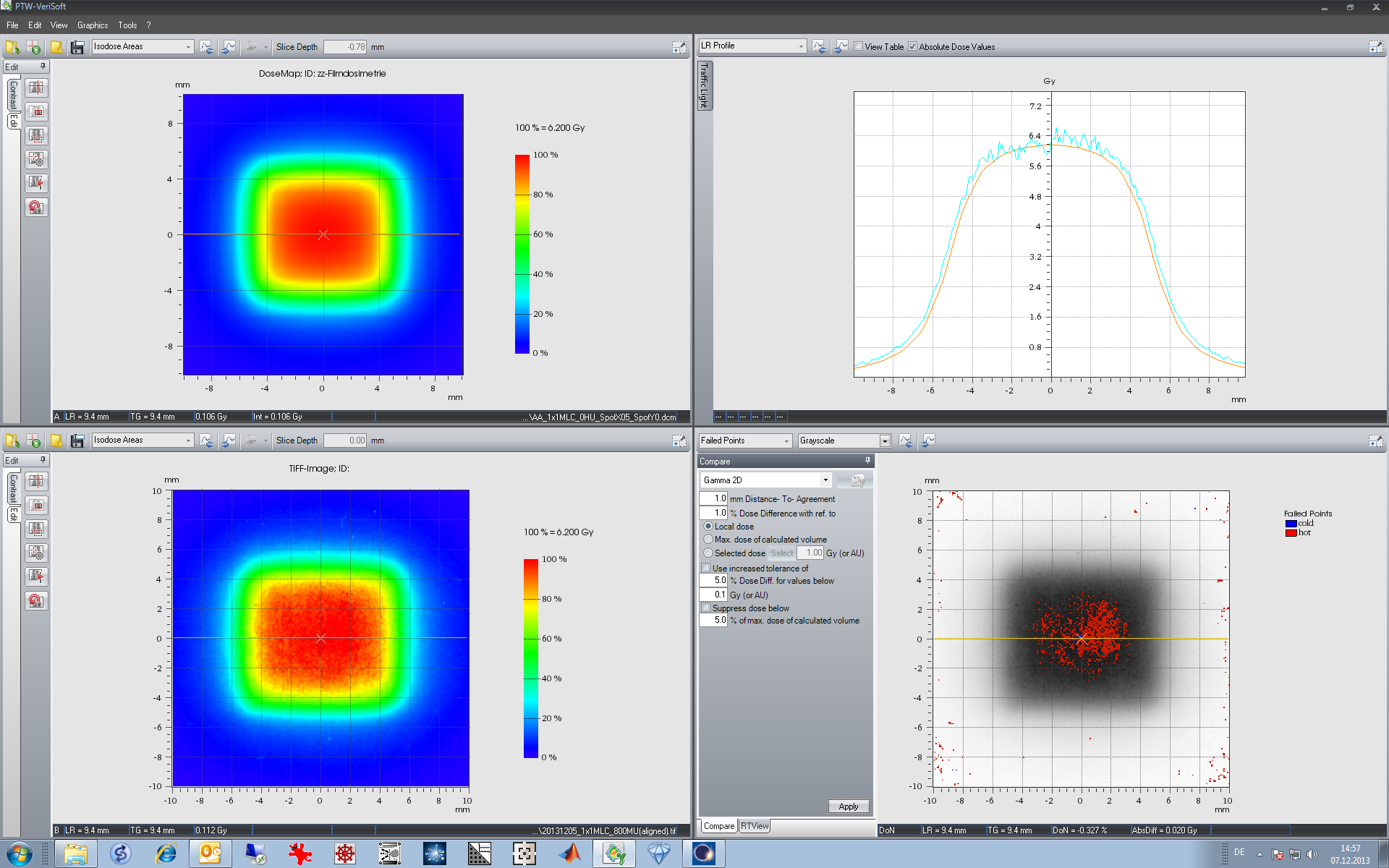
Finally we evaluate the tiny 05x05MLC field.
AAA dose calculated with SpotX = SpotY = 1 mm breaks down:
AAA dose in the center of the field is 15% lower than measured dose. After renormalization, it is easier to compare the shape of the profiles. Measured dose fall-off is steeper both inplane and (to a lesser extent) crossplane.
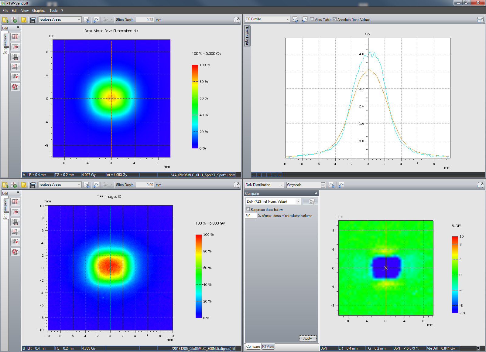
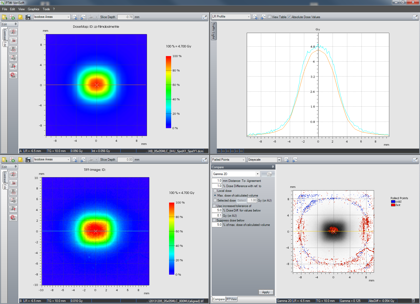
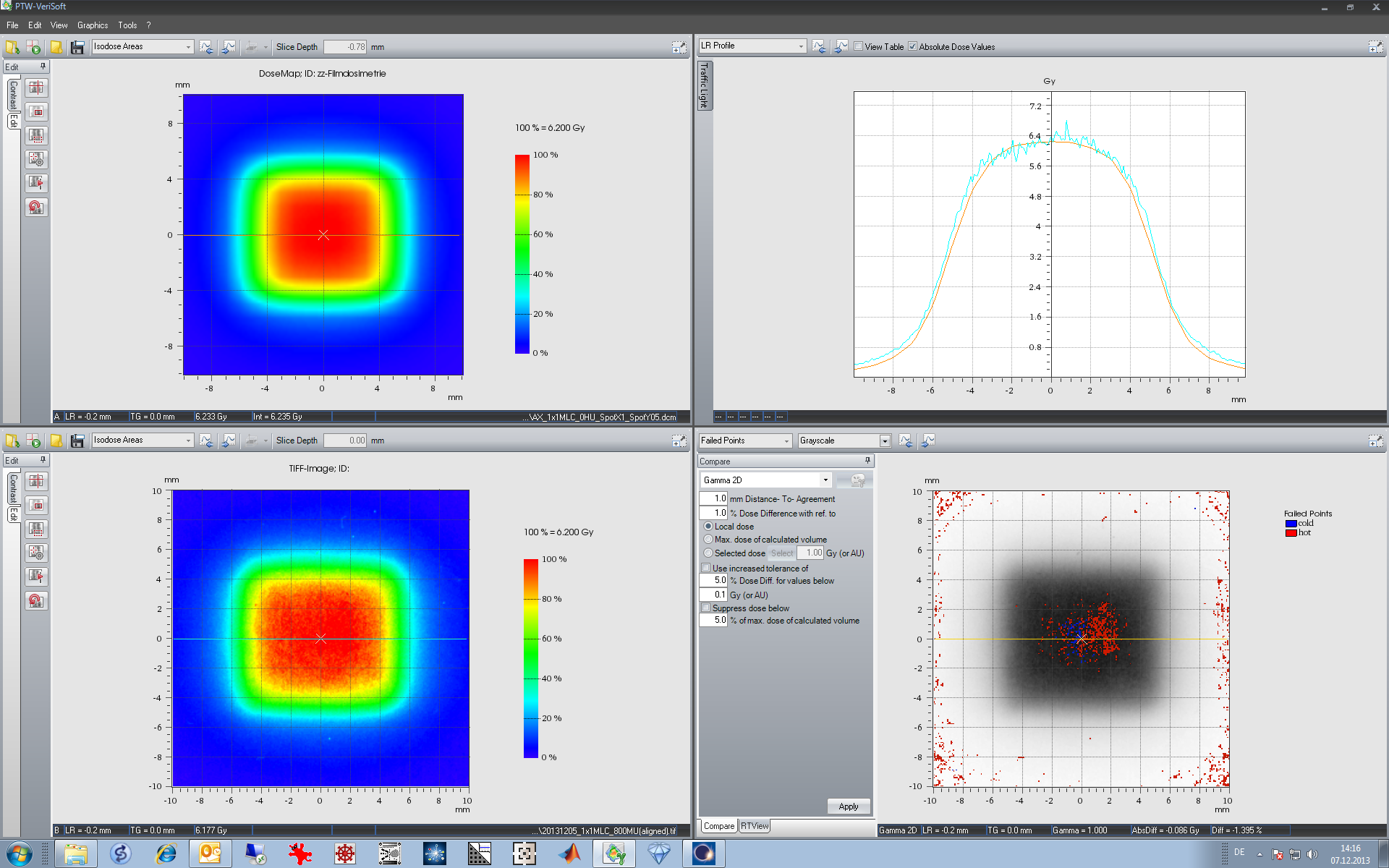
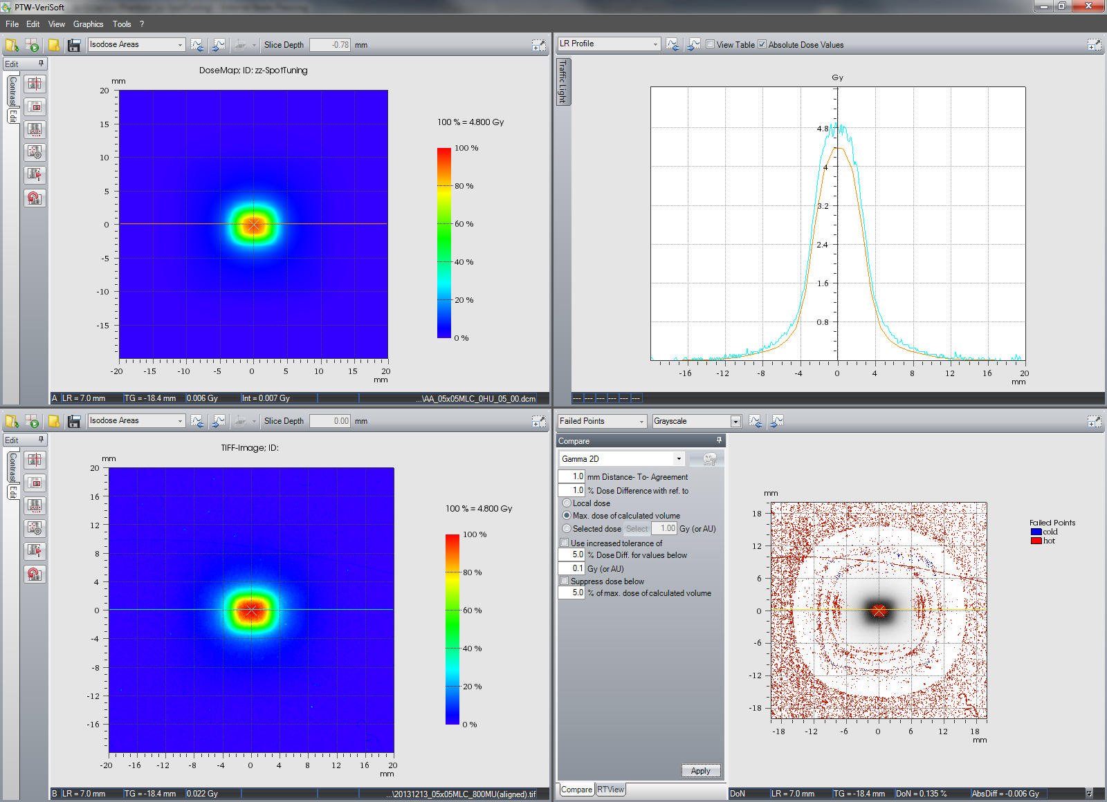
AXB calculation with SpotX = SpotY = 1 mm is clearly better able to model the measured dose of this small field:

Dose difference is "only" 4 - 5%. Again the measured dose plateau (if one can speak of a "plateau" at all) is a little wider crossplane, which we could try to correct by reducing MLCspotX. This would also increase dose at field center.
In other words: from the initial 1 mm, all spot sizes have to come down.
Results: Optimized Spot Sizes
We skip some optimization steps, which went (for AXB) from SpotX/Y = 1/1 over 1.5/0, 0.5/1, 0.5/0.5 to 1/0.5 mm, and just report the final optimization results.
We stopped optimization of AAA MLCspot size at SpotX = 0.5 mm, SpotY = 0.0 mm.
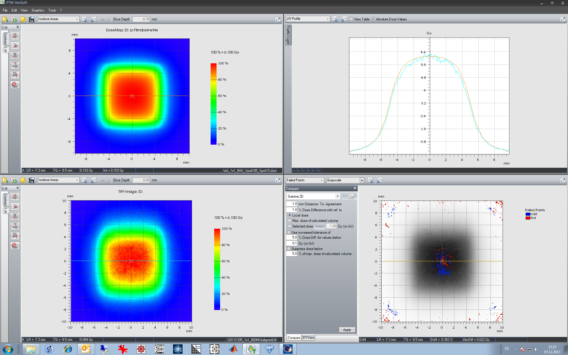
This is the comparison of AAA calculation and film measurement for the 05x05MLC field:
The improvement after optimization is evident. However, calculated dose is a little too low: in the center of the field, it is about 4% smaller than measured dose.
AAA calculated field width in the crossplane direction is still a little smaller than the measured width.
(If dose is considered more important than fidelity of beam shape: a value of SpotX = 0 mm increases dose in the center of the field by about 1%, with still acceptable crossplane profiles. Inplane, there would be of course no change in profile shape.)
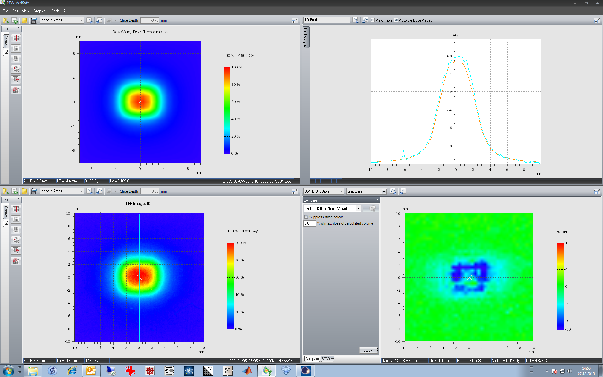
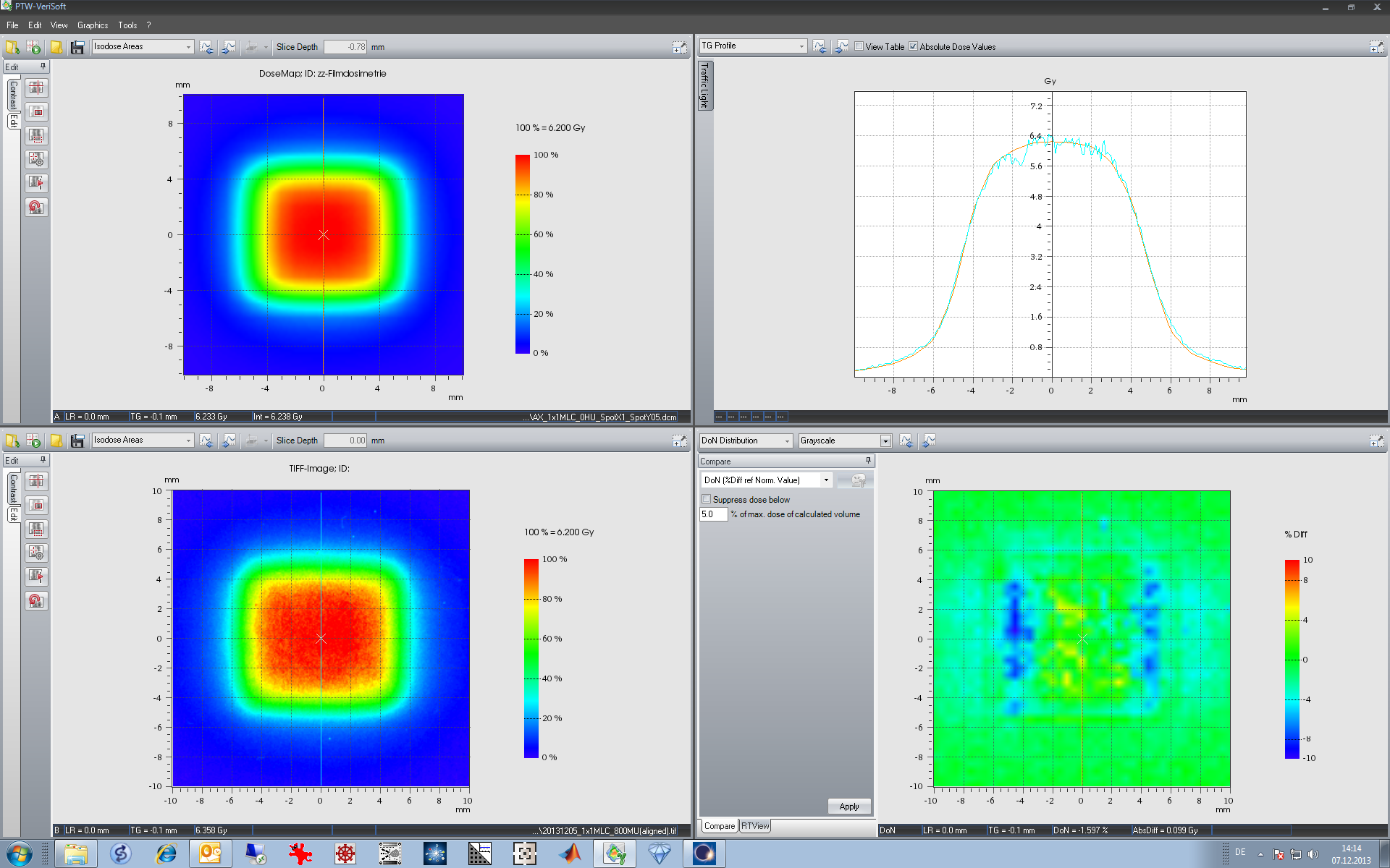
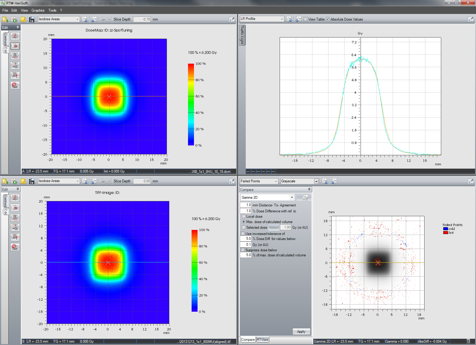
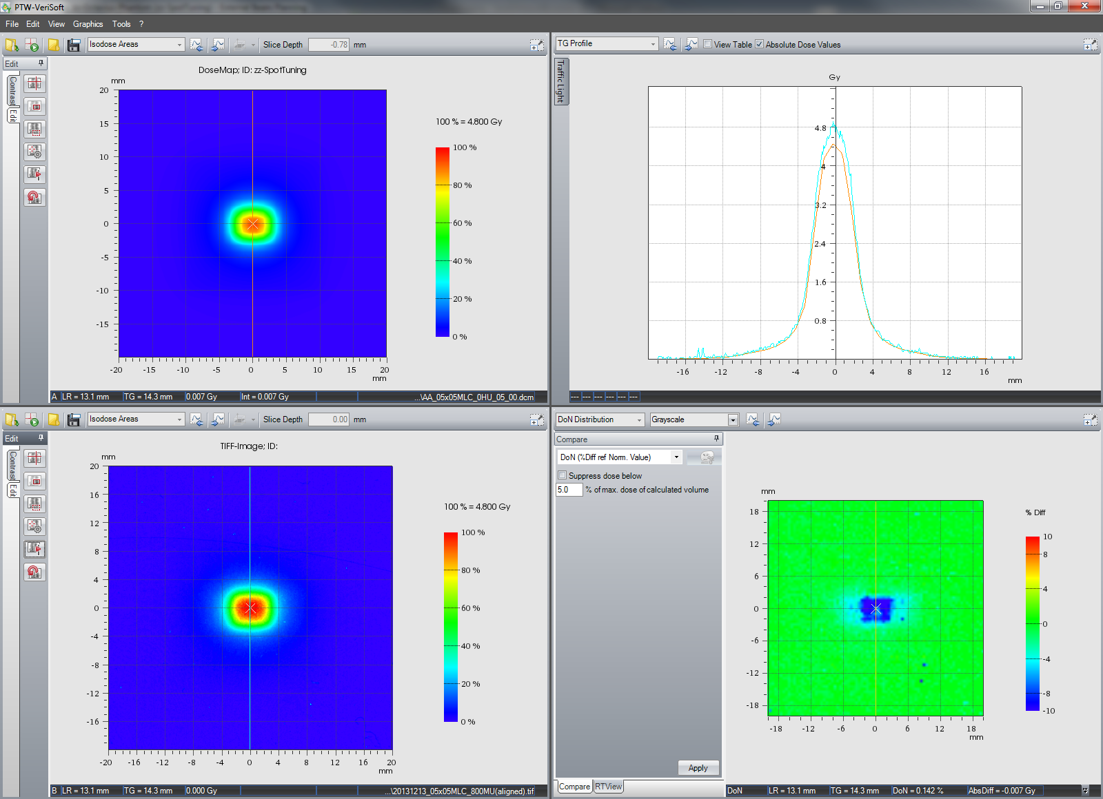
We stopped optimization of AXB MLCspot size at SpotX = 1.0 mm, SpotY = 0.5 mm.
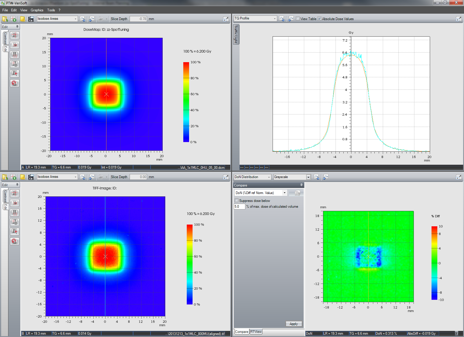
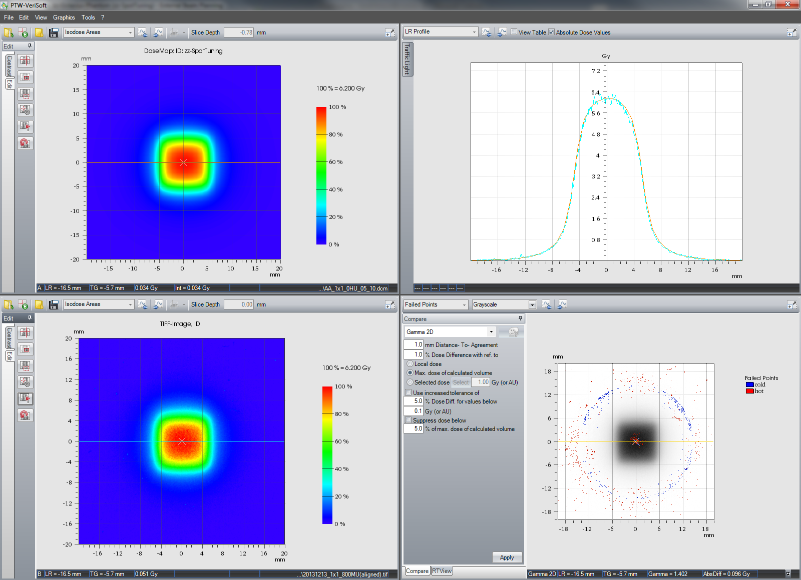
This is the comparison of AXB calculation and film measurement for the 05x05MLC field:

Inplane, measured and calculated profiles agree very well. Crossplane, the situation is similar to AAA. But the absolute dose agreement is clearly better with Acuros XB than with AAA.
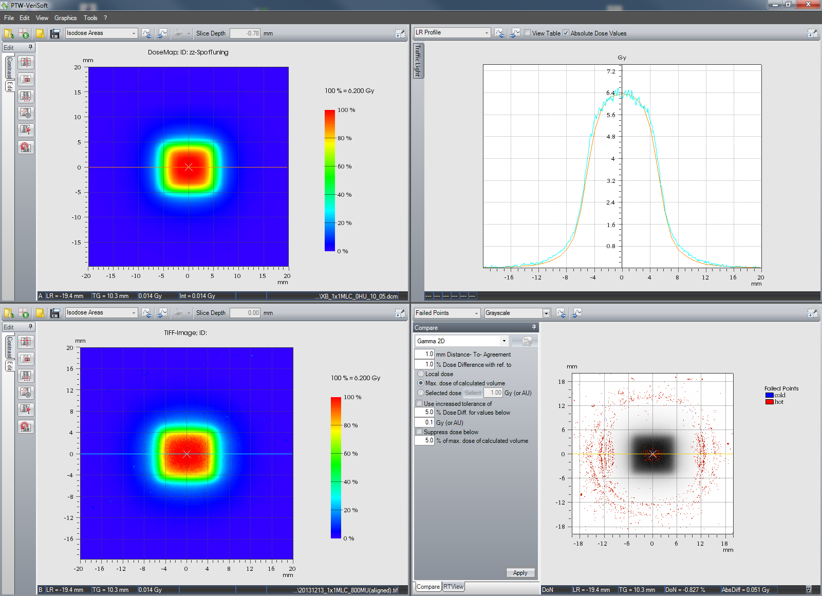
In case you are interested in the 1x1MLC field with the optimized spot size:
- AAA inplane and crossplane,
- AXB inplane and crossplane.
You may ask: what if I calculate a jaw-only 1x1 field with the MLCspot? This is our result for AAA inplane, AAA crossplane, AXB inplane and AXB crossplane, calculated with the spot size optimized for MLC. Inplane, calculated profiles are too "sharp", because the Y jaws, which shape the beam, are much closer to focus than the MLC. This leads to increased penumbra compared to the MLC (and also compared to the X jaws). Crosplane, the shape of the measured profile is well modeled by the "MLC optimized" beam model.
Discussion and Conclusion
Spot sizes can be optimized, so that agreement of both the shape of beam profiles as well as absolute dose improves. It is up to the user at which point to stop the optimization process. The values we found are not meant as recommendations for other users. With a sample of three films irradiated, one cannot expect that! We find our values satisfactory, which does not mean that they are optimal.
The dependency of spot size parameters on the choice of the detector used for beam data measurement was not checked. It cannot be excluded that the optimal values found for a point-like detector are different than for a medium-size chamber.
For AAA, our optimized MLCspot (SpotX = 0.5 mm, SpotY = 0 mm) works well down to 1x1MLC. In X direction, it is smaller than Torsti's (SpotX = 1 mm, SpotY = 0 mm). This is probably due to the different MLC models (our HD120 versus Torsti's Millenium-120). Since the rounded leaf edge shapes the beam in X direction, it is plausible that
- MLCspotX is always larger than MLCspotY (where the leaf edge is not rounded), and that
- MLCspotX for a HD120 MLC is smaller than for a Millenium-120 (the radius of curvature of the former is twice as large).
For AXB, our MLCspotX (1 mm) is also slightly smaller than the value found by Torsti (1.5 mm).
Our optimized MLCspots for AXB are 0.5 mm larger in each direction than the AAA spots (1.0/0.5 versus 0.5/0.0 mm in X/Y direction).
With our optimized spot sizes, it looks like both algorithms perform equally well down to 1 x 1 cm. In the end AXB wins the race, because dose agreement is still excellent at 0.5 x 0.5 cm.
Another result of this study is that our semiconductor Output Factor measurements at 1 x 1 cm were confirmed by film dosimetry.
However, all this was for 6 MV only. The other four photon energies still wait to be optimized3 :-(
Notes
1 In Eclipse Beam Configuration, only one parameter value can be specified per direction.
2 Since most clinical fields have an MLC, beamdata should be measured with MLC fields as well. Varian should switch from jaw-defined to MLC-defined fields (as far as possible) in their beam data aquisition guidelines.
3 "Such experiences lead me to quote from Webster's dictionary of the English language (pre-1960), where we find that the verb 'to optimize' means 'to view with optimism'." (Knuth 2000).
4The 10FFF fields were scanned without flattening correction. For very small fields, the "unflatness" of the scanner is not critical.
More Notes
We repeated the procedure for 10FFF and found the following spot sizes to be quite optimal:
- AAA/MLCspot: SpotX = 0.5 mm, SpotY = 0.0 mm
- AAA/JAWspot: SpotX = 0.5 mm, SpotY = 1.0 mm
- AXB/MLCspot: SpotX = 0.5 mm, SpotY = 0.5 mm (1.0 mm / 0.5 mm is also good)
- AXB/JAWspot: SpotX = 1.0 mm, SpotY = 1.5 mm
Screenshots are for the 1x1 cm field. Spot sizes for 10FFF and X6 are comparable. Without going through all five energies of the TrueBeam: we are quite convinced that the same values can be used for all energies in Eclipse Beam Configuration.
For the AAA calculated 05x05MLC field, the situation is similar to X6: dose in the center is too low (SpotX = 0.5 mm, SpotY = 0.0 mm). Using SpotX = 0.0 mm , SpotY = 0.0 mm increases dose a little.
If the 05x05MLC field is calculated with Acuros XB, agreement is much better (SpotX = 0.5 mm, SpotY = 0.5 mm).