| |
The Half-Lung |
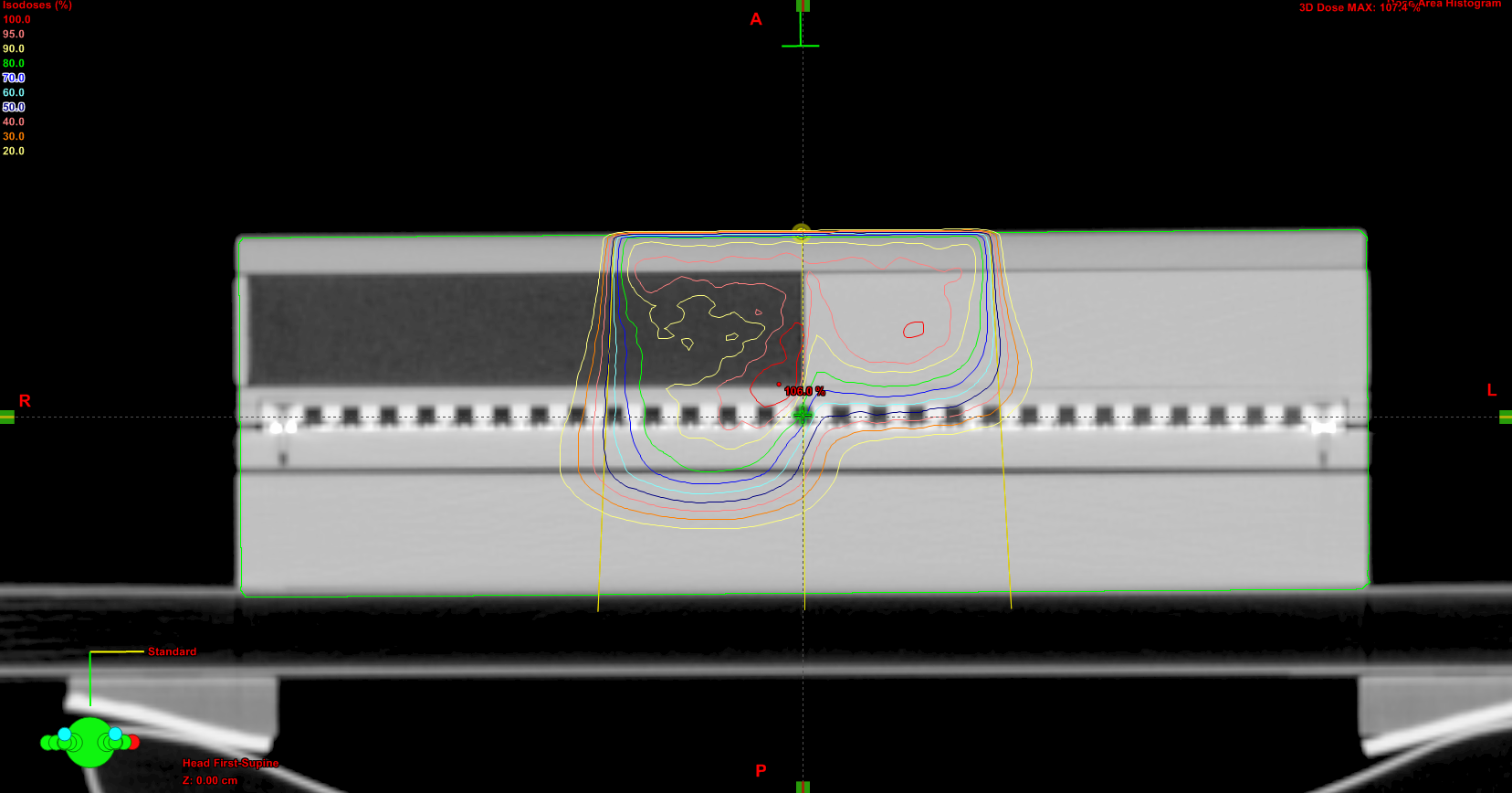
The Half-Lung uses the PTW 2D-ARRAY (center), Cork (left buildup), PMMA (right buildup and below the Array) and RW3 (solid water, on top) in the following assembly: |
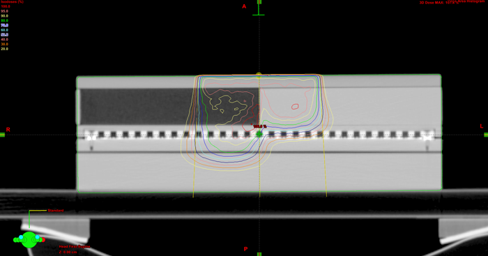 |
| The idea is to test eMC's capability to deal with heterogeneities. The Phantom is CT scanned and different plans are created. The 2D-ARRAY measures the planar dose distribution. After the corresponding plane is exported from Eclipse, the evaluation can be made with VeriSoft. |
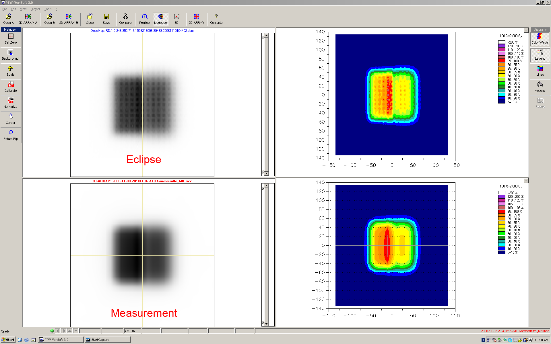
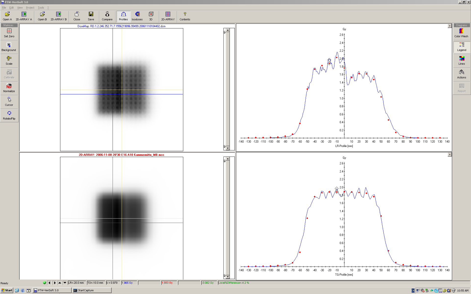
| If Smoothing is switched off in eMC and a grid of 1mm is used, the calculated plane shows fine details: |
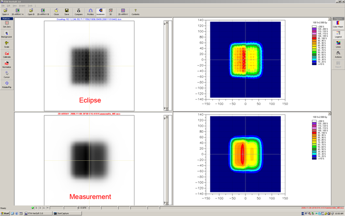 |
| Calculation without smoothing reveals more inhomogeneities in the phantom (the ionization chambers are filled with air). The nominal distance between the measuring points is 10mm, the agreement at the chamber locations is good: |
 |
| |
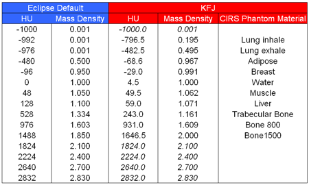
| The Mass Density Calibration |
The eMC does not calculate based on relative Electron density, but on Mass density. Therefore, it is a good idea to check the validity of the default mass density calibration curve in Eclipse. |
|
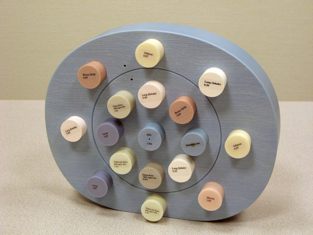
| With the CIRS Density Phantom Model 62 (above), we found out that the default mass density calibration of Eclipse works fairly well with our CT scanner (Somatom Plus 4), but should be modified in the medium HU range between 400 and 1800HU: |
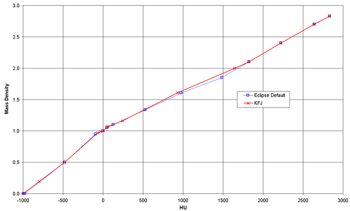 |
| Above 1800HU, we use the default data, since the CIRS Phantom has only one Sample (a Ti-rod) beyond this point. |
|