A simple example shall explain the basics of dynamic multileaf collimation. This is a synthetic leaf motion pattern, that has only three distinct "key shapes":
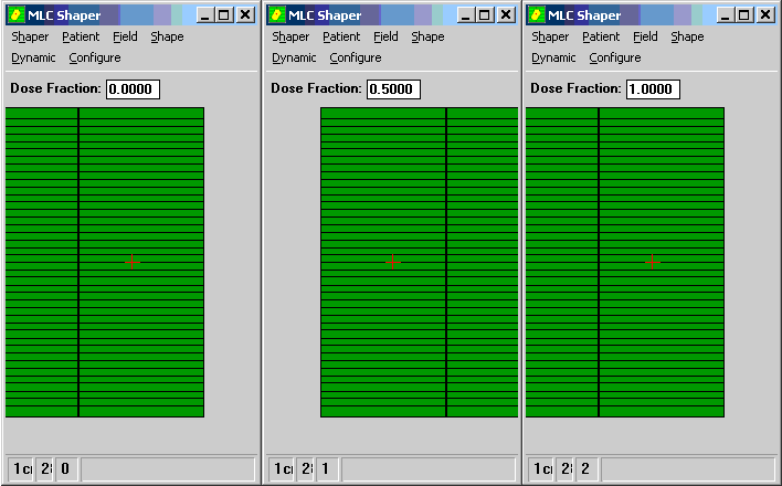
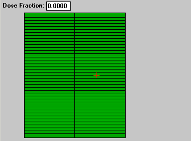
These three screenshots define the complete DMLC sequence. At dose fraction 0.0000, all leaves are to the left (the red cross marks the central axis). The left carriage on each screenshot is carriage B, the right one carriage A. The leaf coordinates of each leaf count positive from the midline outwards, the first shape has all B-values at +7.5cm, all A-values at -7.0cm, therefore the leaf gap is 5mm wide. The middle shape has A-values at +7.5cm, B-values at -7.0cm. The right shape is identical to the left shape, except that its dose fraction is 1.0000, which defines the end of the treatment.
Each leaf travels 29cm during the treatment (14.5cm to the right, then back). For calculating the duration of the treatment (and the leaf speed) one has to specify two more values: the dose rate (DR) and the monitor units (MU). With DR=600MU/min (10MU/sec) and 200MU, treatment will take 10sec and leaf speed will be 1.45cm/sec@isocenter. During testing, one is sometimes interested in the maximum possible leaf speed. Then the reverse calculation has to be performed: to move the leaves at 3cm/s, with DR600 the necessary MU setting would be 97MU.
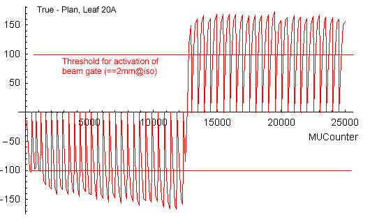
There is one more important parameter: the "dynamic plan tolerance" defines the maximum deviation of each leaf from its planned position during delivery. If this tolerance (typical value 2mm@isocenter) is exceeded, the beam gate is activated. This means that the Clinac's gridded gun shuts off the beam to prevent the machine from irradiating "wrong spots". This gives the leaf time to "catch up" and when it is within tolerance again, the beam instantly is activated. This is a matter of milliseconds.
Leaf trajectories can
be plotted in different ways, e.g. leaf positions as a function of time or
leaf positions as a function of dose. The planned leaf positions as a function
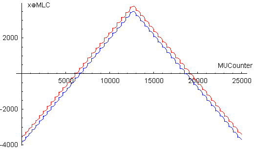
of dose, taken from the DynaLog files, can be seen in the next figure, for
leaf pair 20 (all leaf pairs are identical in this example). The B-leaf (left
leaf in Beam's-Eye-View) is always drawn in blue, the A-leaf in red. The dose
fraction in the DynaLog files always runs from 0 to 25000, that has to do
with the internals of the MLC controller. 25000 simply corresponds to 100%
MU (or dose fraction 1.0000 in the above screen shots).
The vertical axis is the leaf position at MLC level. 100 raw units correspond
to 1mm at MLC level (or 1.96614mm at isocenter), so 1/100mm is the resolution
of the DynaLog positions at MLC level. We will use MLC level and raw units
throughout this site unless otherwise mentioned.
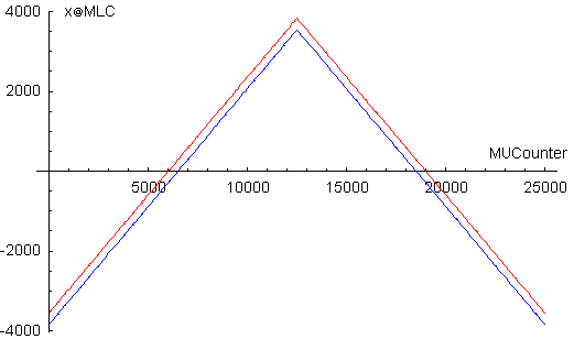
The attentive reader will notice that the positive direction of the B leaf has been reversed (this will be done for all trajectory plots).
While executing the DVA file, the MLC controller permanently interpolates the necessary leaf positions (for each leaf separately) depending on the current dose fraction. This is always a linear interpolation. The example uses only three distinct MLC shapes, a clinical file can contain up to 320 shapes (Millenium MLC: 400).
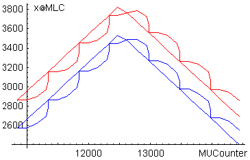
The next plot shows the true trajectories as a function of dose. Because leaves are required to travel at 3cm/s (MU setting was 97MU), the beam gate is activated permanently, which leads to the curly trajectories. The cutout shows all four trajectories (true + plan) at the point where leaves change direction. The dynamic plan tolerance sets the limit how far true positions may deviate from plan positions.
By subtracting the planned leaf positions from the true leaf positions, one receives the "leaf position errors" during the treatment, here shown for leaf 20A: