Most measurement systems on the market which are based on 2D-arrays and which are used for the verification of rotational therapies like RapidArc or Tomotherapy exhibit a directional depencence of detector sensitivity. Some systems perform software-compensation after capturing the Gantry angle in real-time with the help of a clinometer. In contrast to such systems, Octavius does not need Gantry readings to know where the beam comes from! The compensating air cavity in the lower half of the LINAC phantom automatically takes care of the compensation.
"Less parts" usually means "higher reliability".
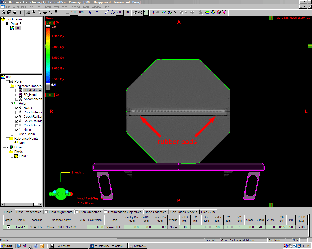
Bending air*
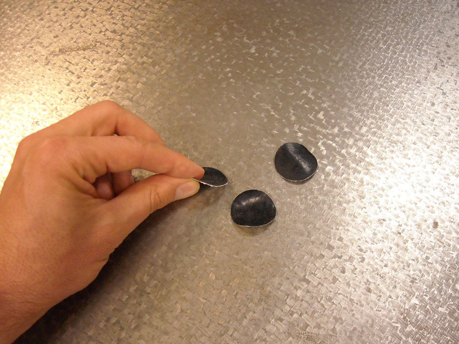
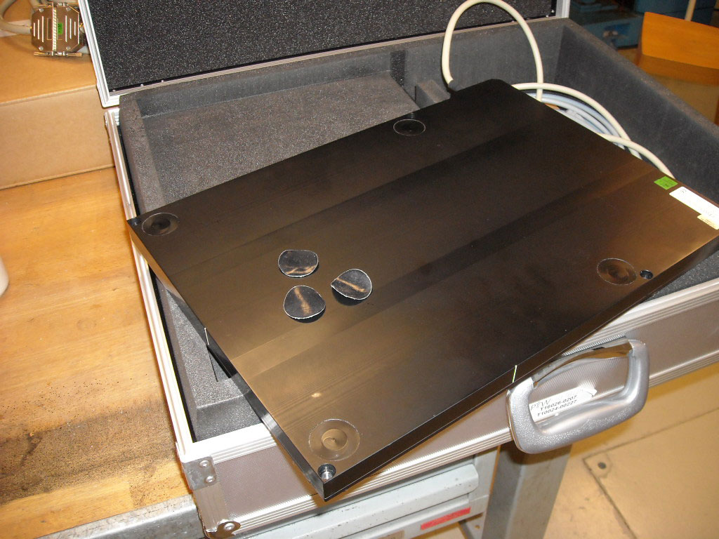
The semicircular air cavity is usually never seen on a CT scan, because the lower part of the phantom which contains the cavity is used during ARRAY measurements only. But for the curious, here is a scan which shows the air cavity (and the chamber inserts instead of the seven29):
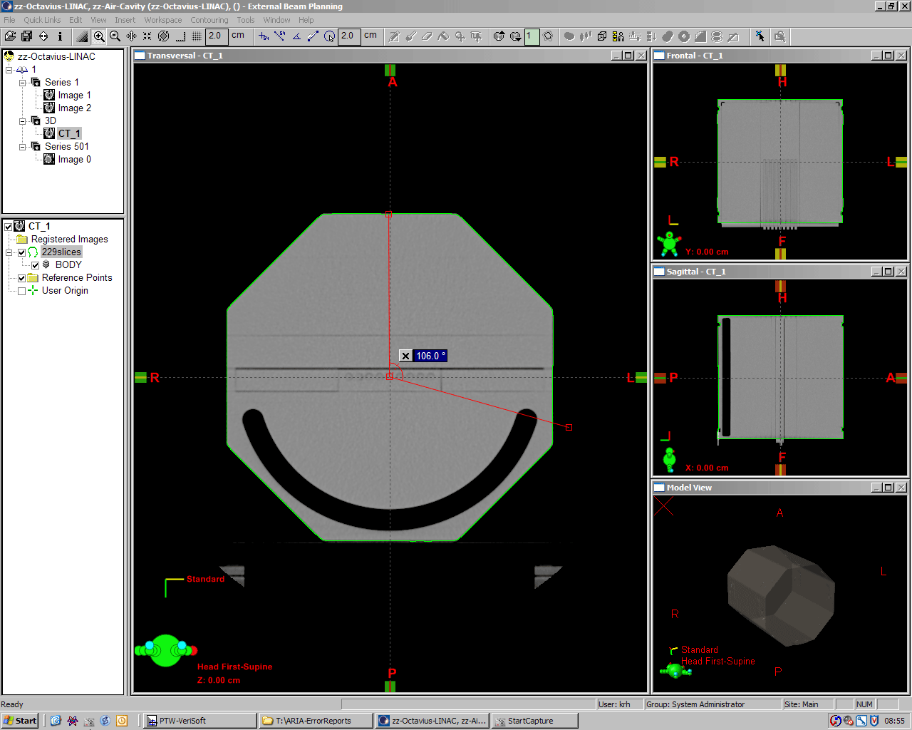
(click to enlarge)
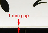
The cavity starts at Gantry angle 103.2° and reaches its full width of 2 cm at 106°. With the ARRAY in place, compensation of the central chamber's signal is effective between 106° and 254°.
The ARC test
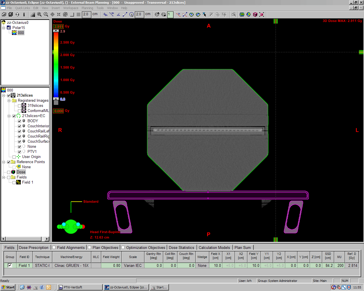
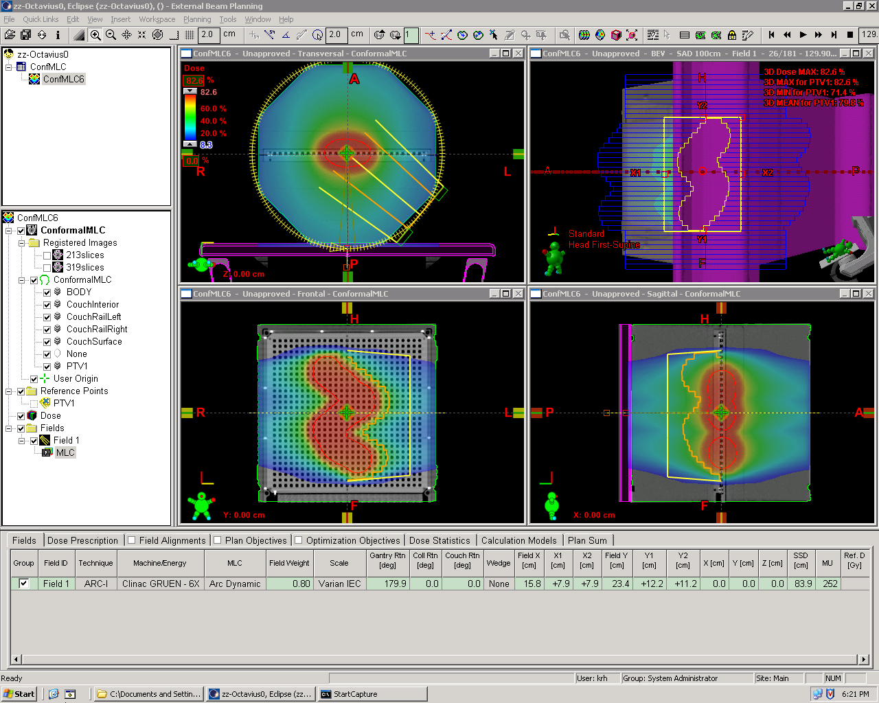
The magnitude of compensation which the air cavity provides can be calculated without performing any measurements. We constructed two semi-ARC treatment plans in Eclipse and compared them. One ARC plan ("UpperARC") runs clockwise from 270° to 90°, the other plan "treats" the lower part of the phantom, where the beam crosses the air cavity (Technically, the lower ARC had to be split into two subARCs). Dose to isocenter was calculated with 200 MU fixed, using AAA 8.6.14. Field size was 10x10 cm. The couch was not modeled, since this would spoil the comparison.
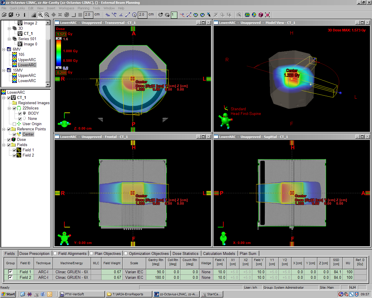
The following image shows the UpperARC plan for 6MV. Calculated dose to isocenter is 1.258 Gy for 200MU:
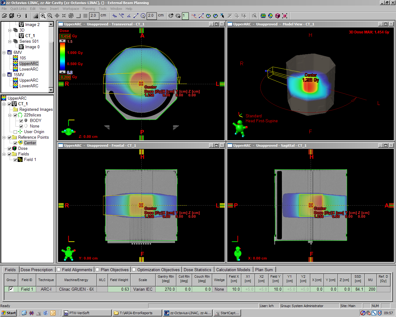
(click to enlarge)
A screenshot of the LowerARC (6MV) is here.
| Plan (200MU) | Isocenter Dose, 6MV | Isocenter Dose, 15MV |
|---|---|---|
| UpperARC | 1.258 Gy | 1.574 Gy |
| LowerARC | 1.338 Gy | 1.642 Gy |
| Dose increase | +6.36% | +4.32% |
Dose is higher by 6.36% and 4.32% (for 6MV and 15MV, respectively), when the beam crosses the air cavity (LowerARC plans). This is to give an idea of the amount of compensation during rotational treatments.
Static fields
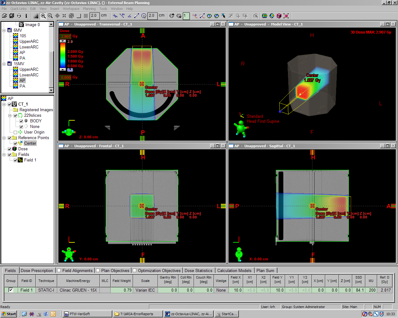
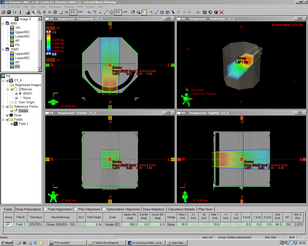
Simple static AP/PA plan comparisons give slightly higher factors:
| Plan (200MU) | Isocenter Dose, 6MV | Isocenter Dose, 15MV |
|---|---|---|
| AP (Gantry 0°) | 1.274 Gy | 1.587 Gy |
| PA (Gantry 180°) | 1.374 Gy | 1.671 Gy |
| Dose increase | +7.85% | +5.29% |
Note that these were evaluations in the treatment planning system alone. The next step is to do some measurements with the seven29/Octavius combination.
How good does it work?
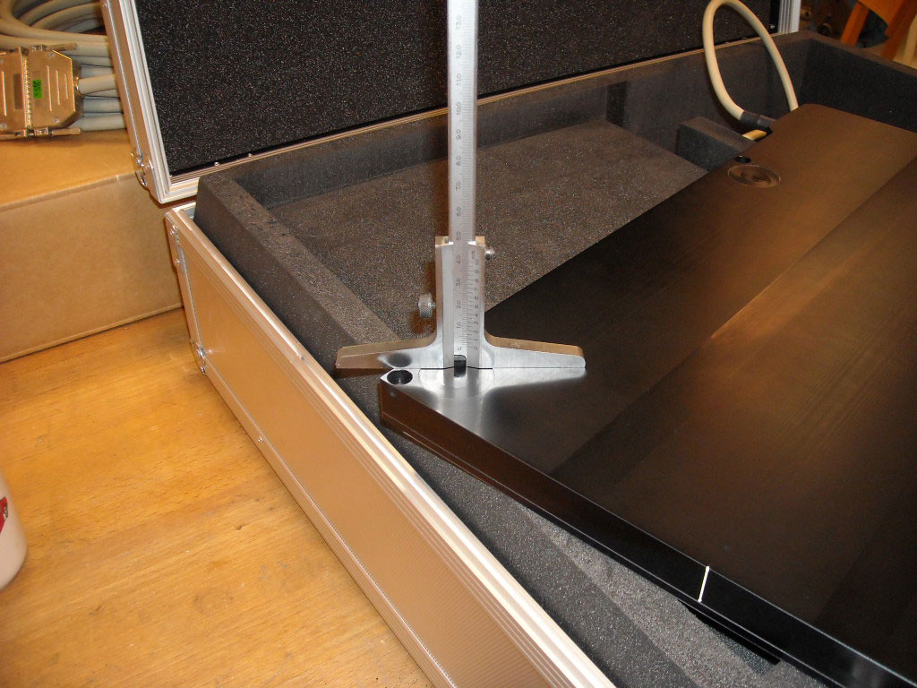
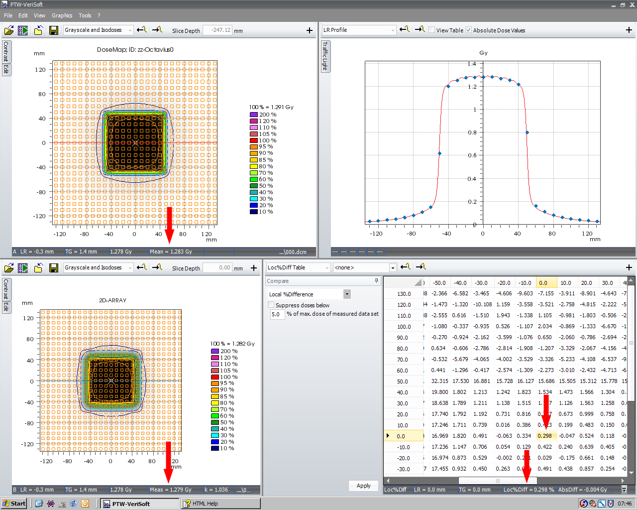
For each energy, 37 isocentric treatment plans were created in Eclipse. Each plan contained a single static 10x10-field (200 MU) with the isocenter in the center of the ARRAY's central chamber. Gantry angle increased from 0° to 180° in 5° steps. The Exact couch was modelled with the rails on the outer position. AAA dose calculation grid size was 1.5 mm. The dose planes through isocenter were exported as 512x512 pixel matrix (size of matrix: 27x27 cm).
The following animation shows the crossplane profile through the ARRAY center for 6MV (here is a zipped MPEG-4 QuickTime movie). Lines are the AAA calculation, dots are the ARRAY measurements. Linac dose rate was 600 MU/min. The first frame is at 0°, the last at 180°. Gantry increment between the animation frames is 5°:
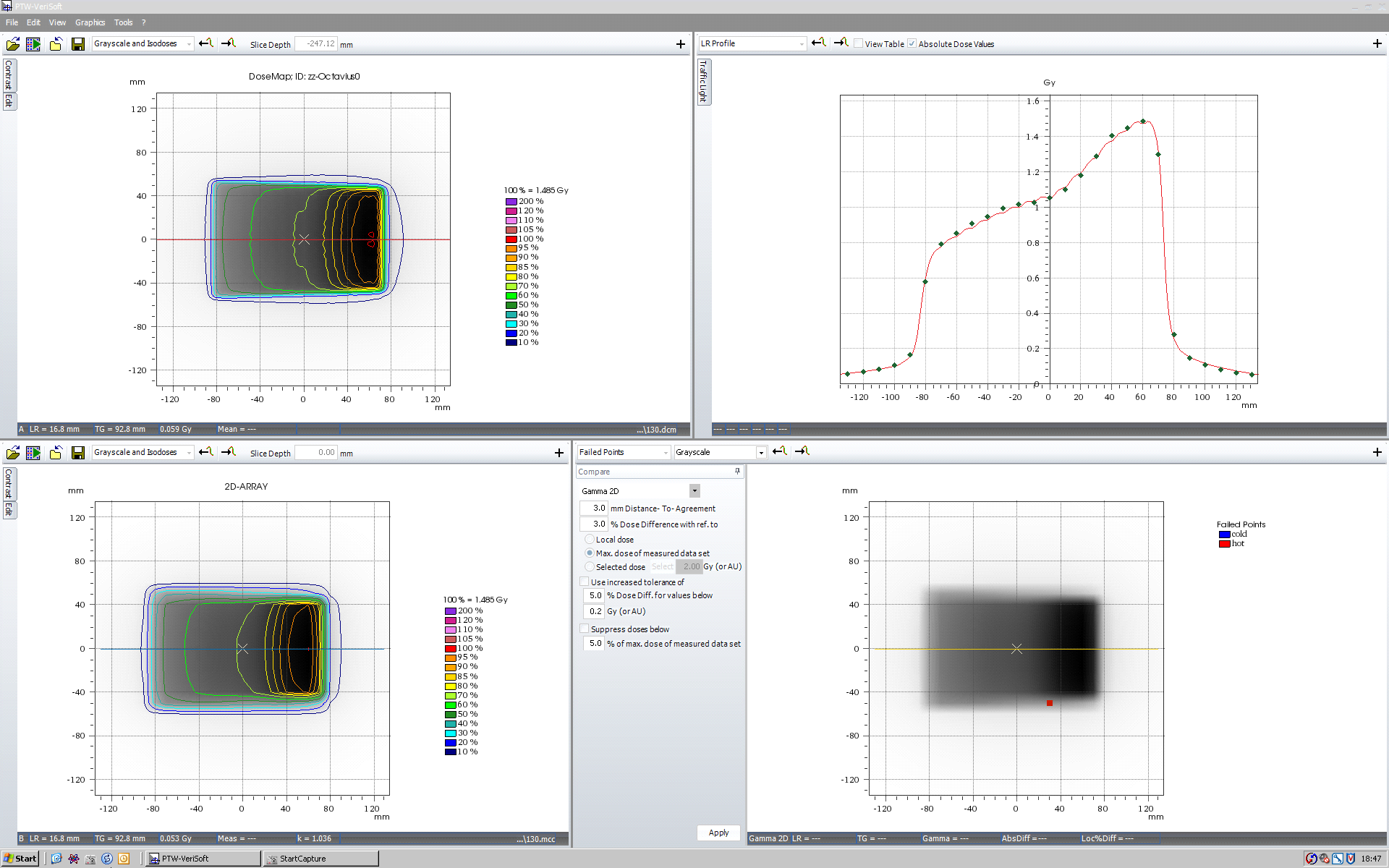
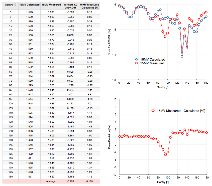
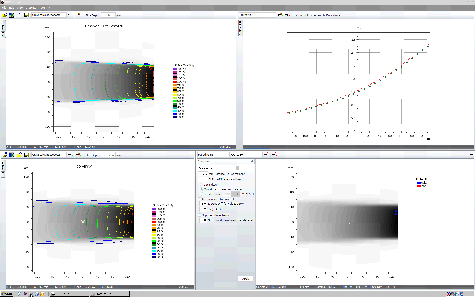
The measured isocenter dose and the Eclipse dose are compared in the following table for 6MV:
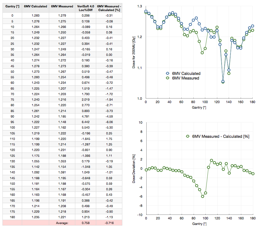
(click to enlarge)
Each point is a single 200 MU measurement (no averaging over multiple measurements) with 600 MU/min dose rate. The zero level of dose deviation has no significance. During the first measurement at Gantry 0° it was tried to adjust kUser such that dose deviation is zero. To give the "Average" value in the last row some significance, one should add 0.31% to the values in the last column, thereby "normalizing" the dose deviation values to Gantry 0°.
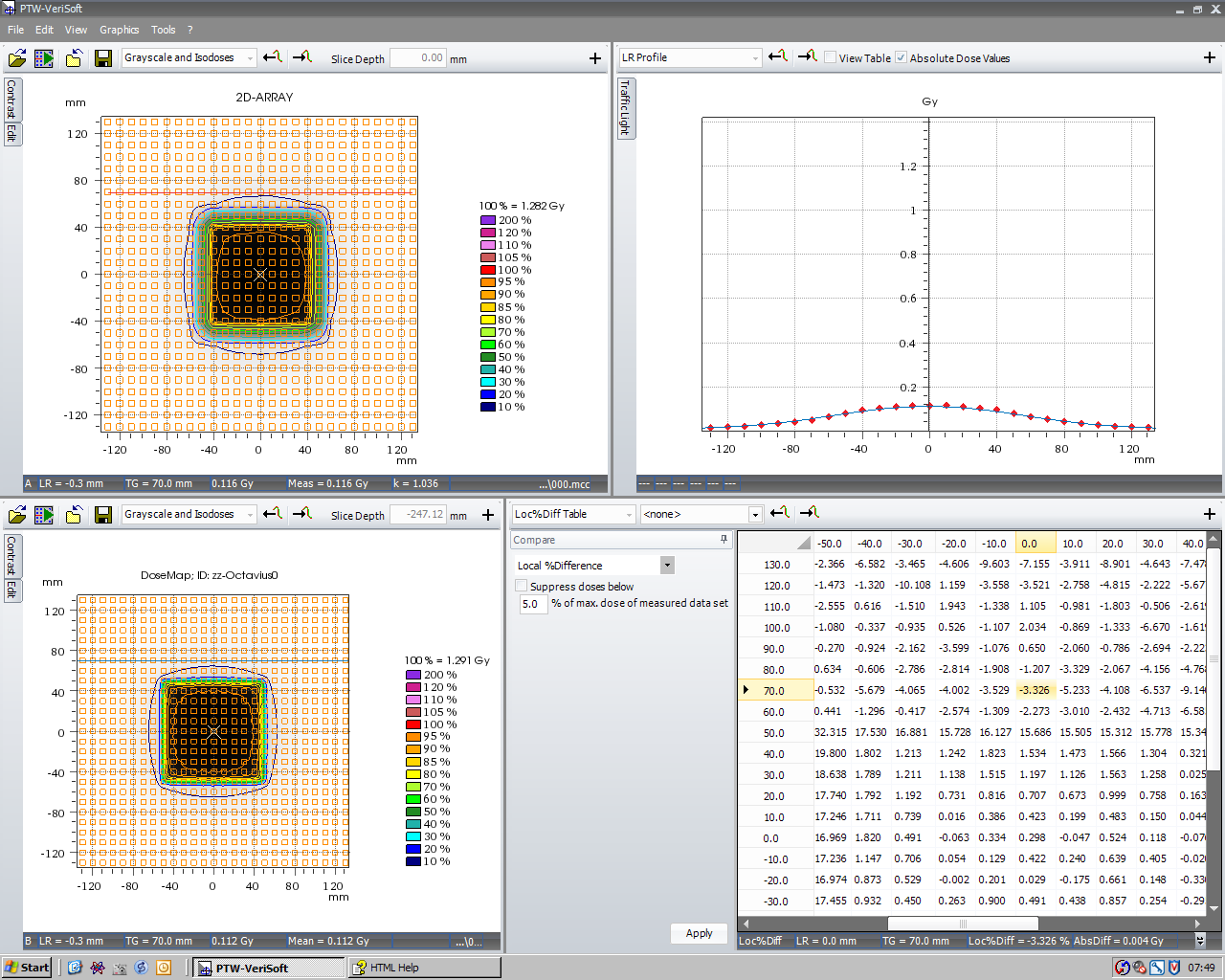
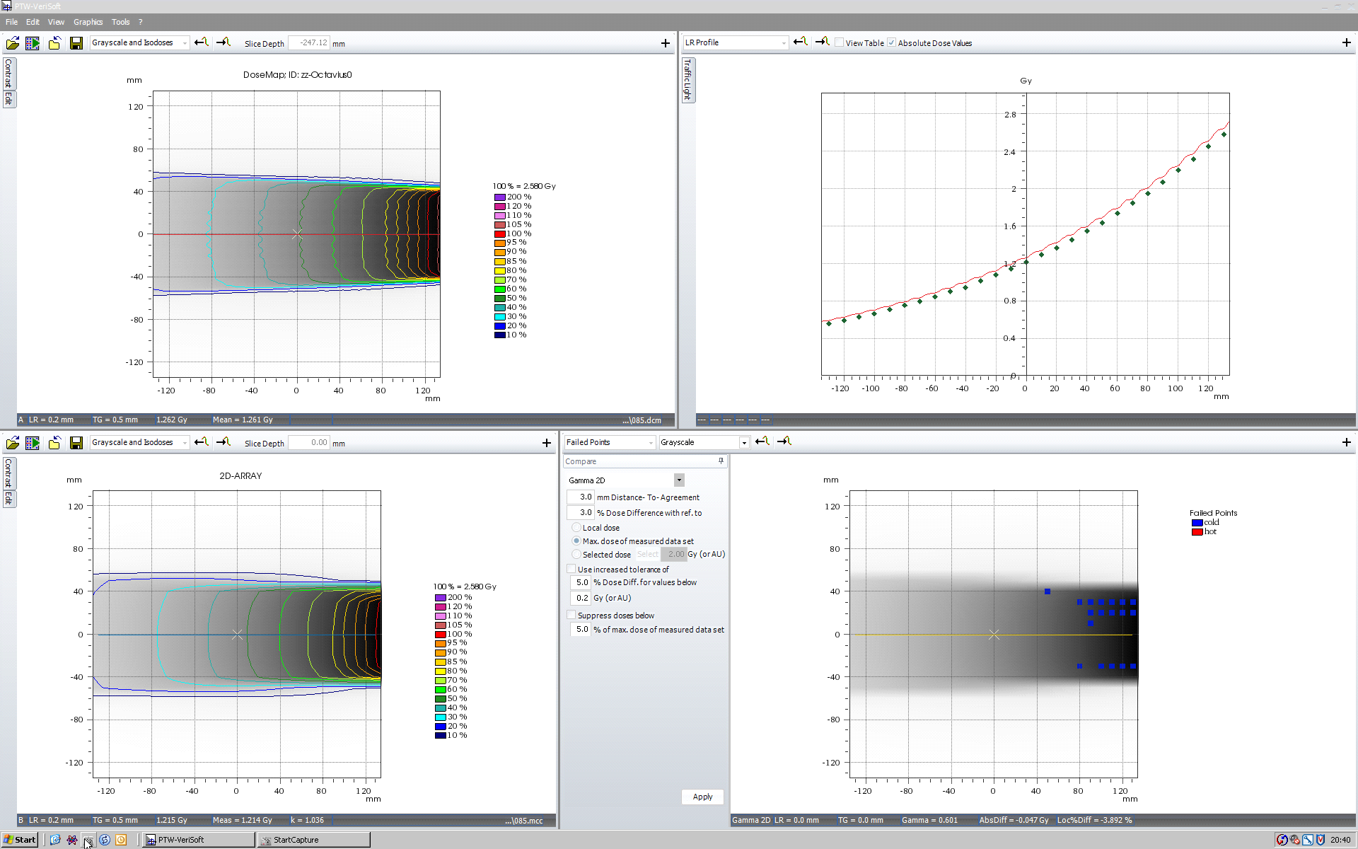
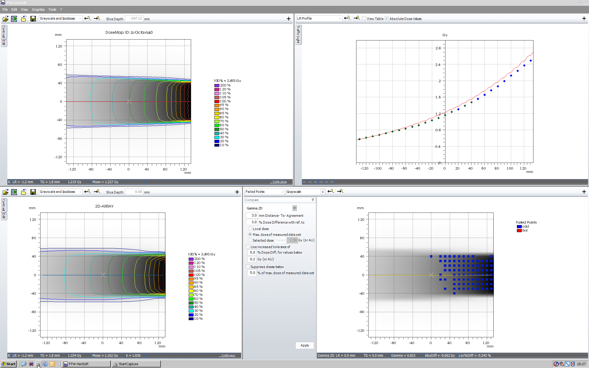
A note on the sign in the deviation plots: positive deviations mean that measured dose is higher than calculated dose (see discussion in the side panel). Between 80° and 100°, agreement is suboptimal, as Ann would call it. The deviation is >2%. The effect of the carbon rail is visible between 130° and 140°.
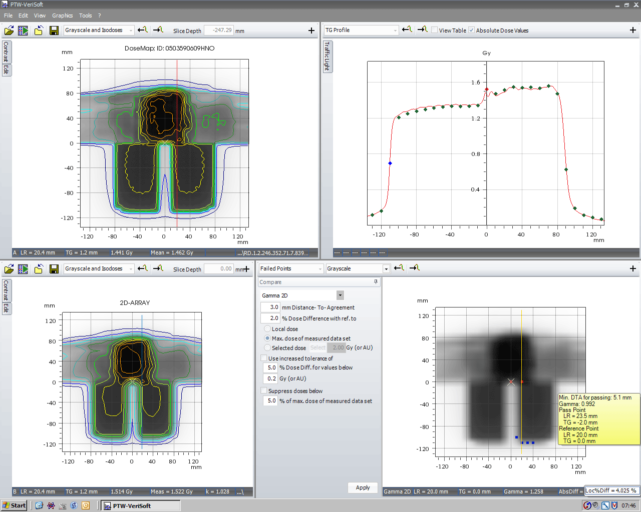
As expected, the central chamber is fully compensated by the air cavity starting at 105°. At this angle, the right part of the profile still suffers from the lack of compensation:

(click to enlarge)
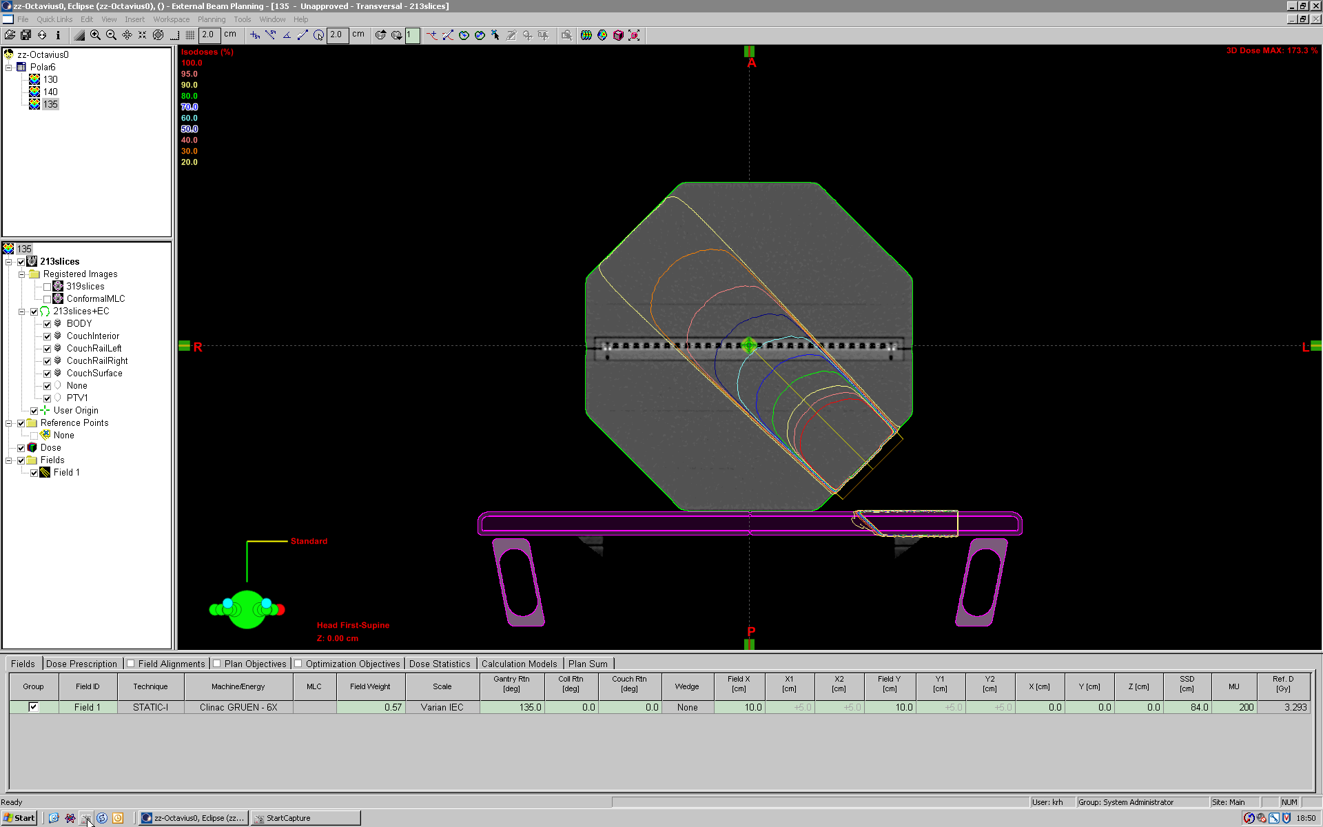
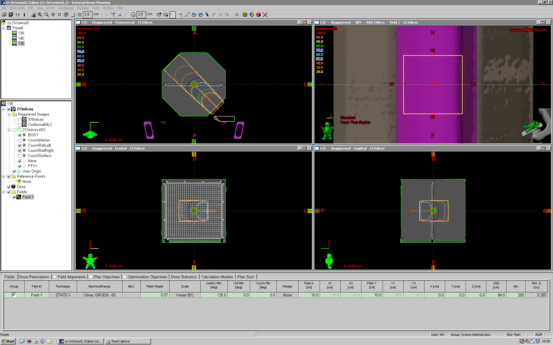
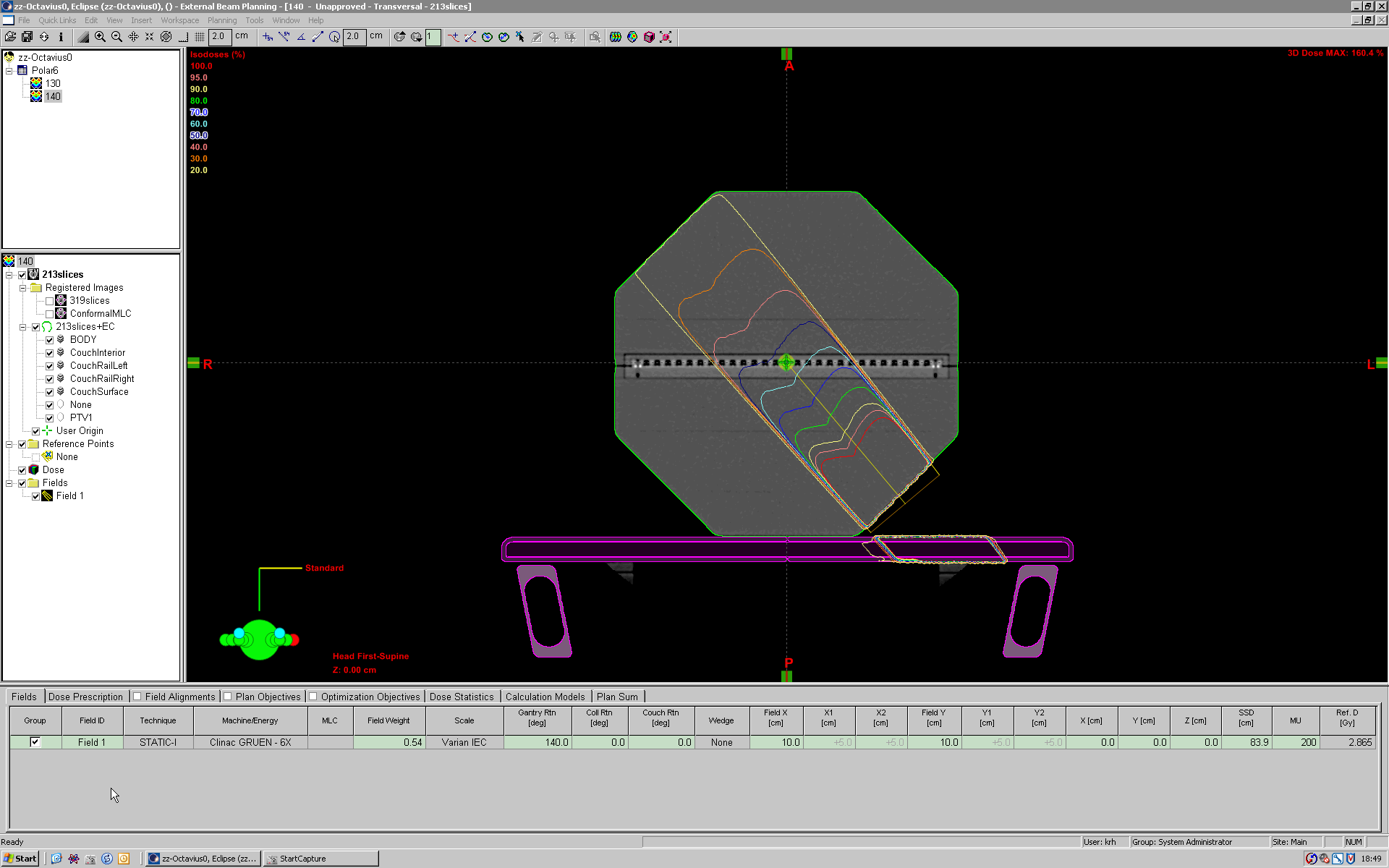
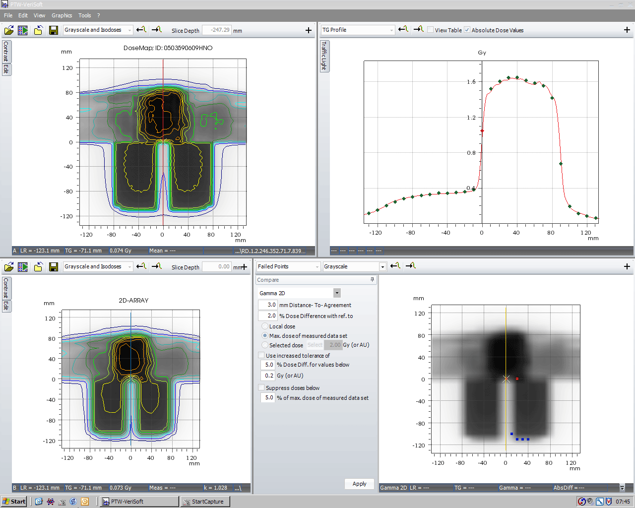
At 130° and 140° (but not at 135°) there are kinks in the profile:
(click to enlarge)
The kinks originate from the massive upper and lower walls of the transversed carbon rail. At 130°, the central axis is in the shadow of the upper carbon wall:

(click to enlarge)
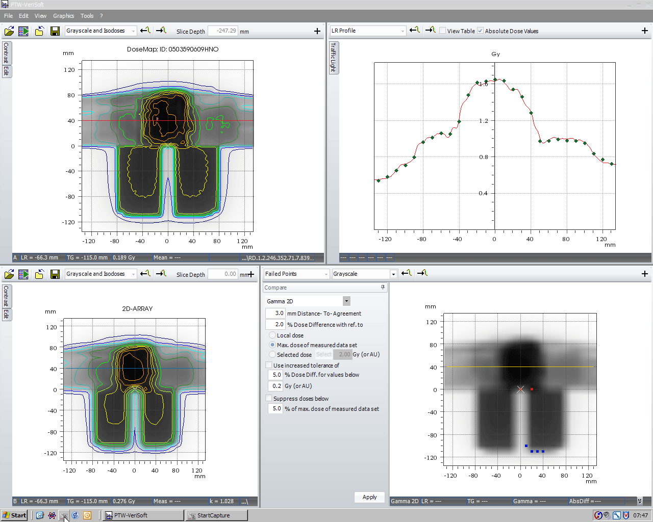
At 135°, the beam is centered in the rail, at 140° the lower wall of the rail shadows the central axis. In all cases, the performance of Octavius and the couch modelling of Eclipse is optimal.
The results for 15MV are naturally better than for 6MV, due to higher penetration:
(click to enlarge)
Clinical Applications
We currently use the seven29/Octavius combination for the verification of fixed-field head and neck IMRT plans.
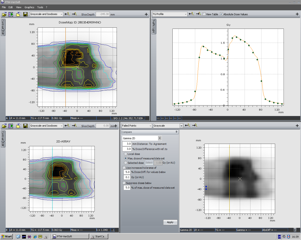
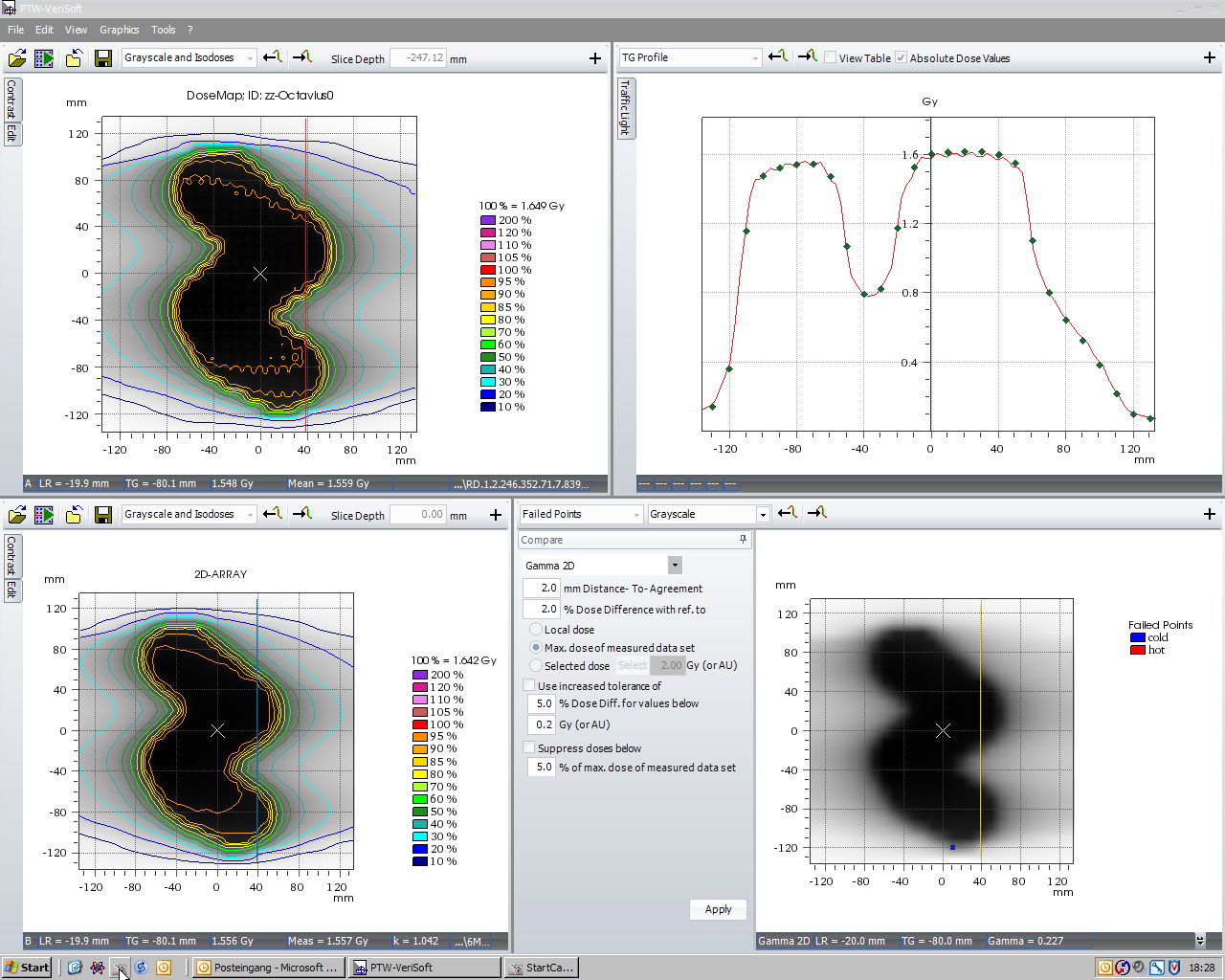
If there are abutting fields, we are usually interested in the abutment region (where the IMRT plan and the forward-planned Supra field meet):
(click to enlarge)
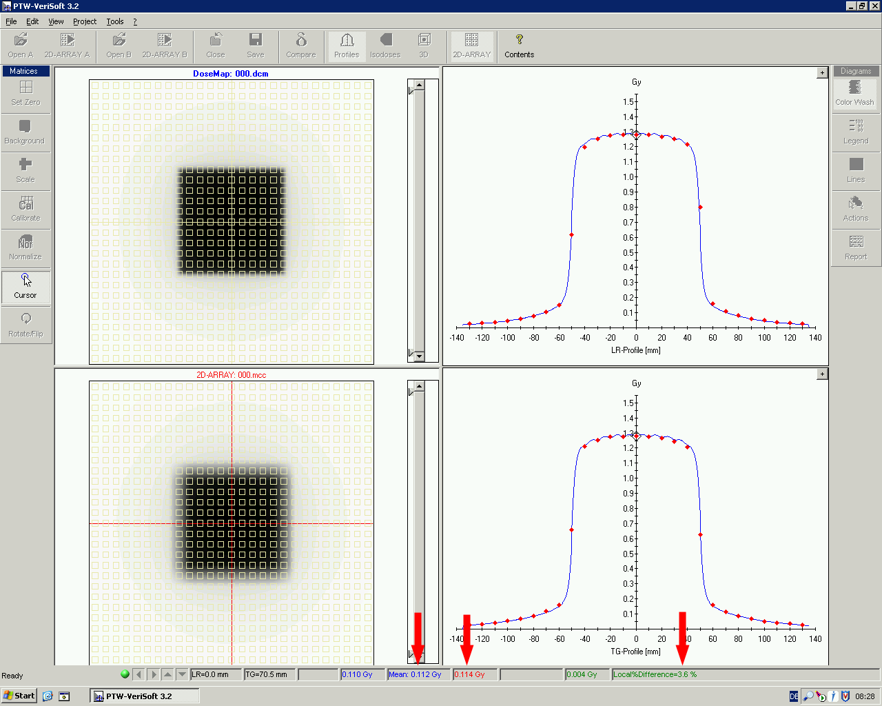
Here is another screenshot of the same plan. A relatively tight Gamma criterion (3mm/2%) was chosen, although the beams enter from multiple directions. Also the lateral dose profiles through the IMRT region usually agree very well.
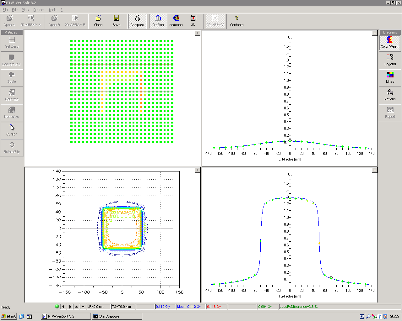
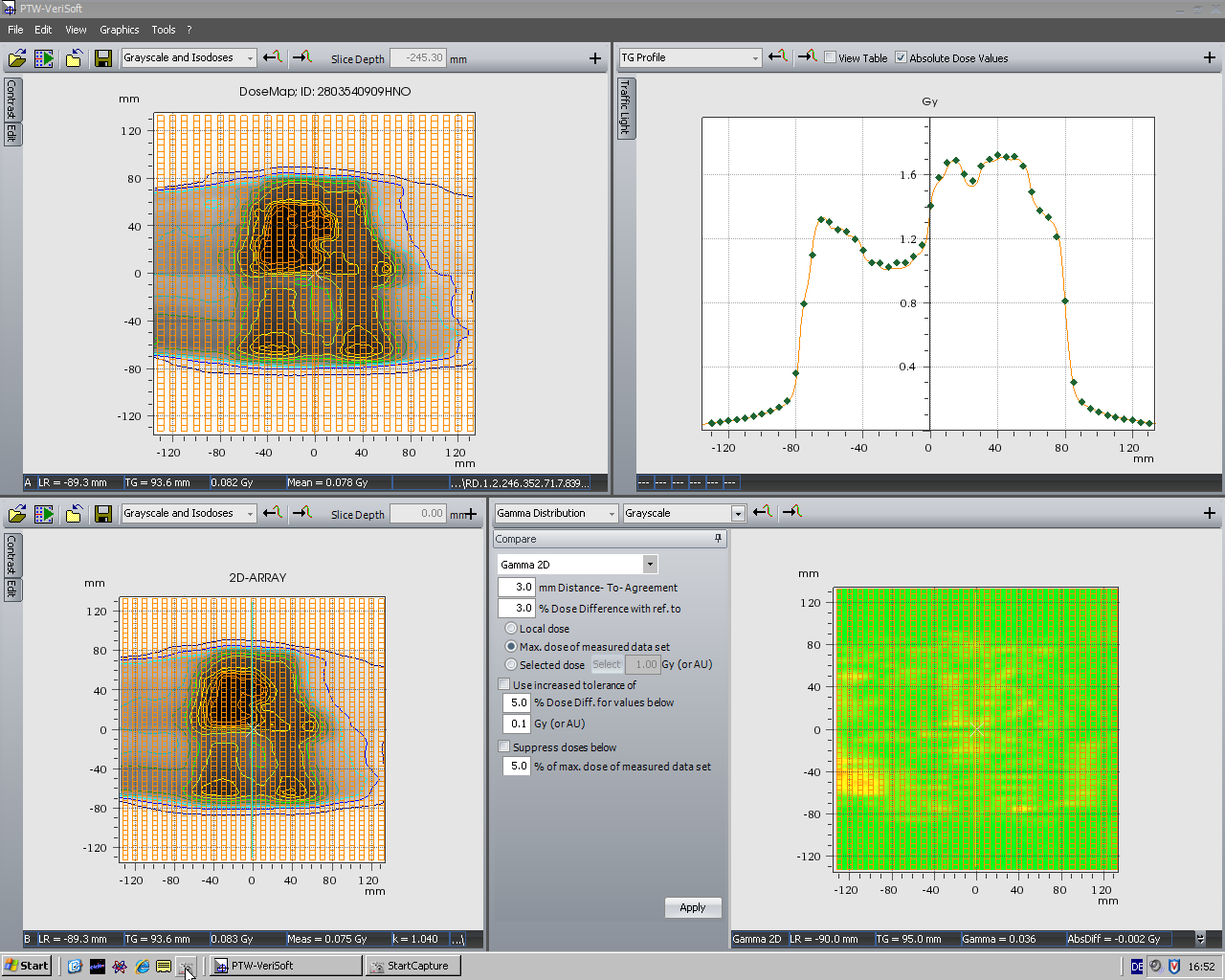
The decreasing sensitivity of the ARRAY between ~80° and 90° (or 270° and ~280°) should not be overvalued! Here is another clinical 6MV IMRT plan where one of the beams enters at a "dangerous" 274°:
(click to enlarge)
But it is only 1 out of 5 beams - the verification result is OK.
Measurement resolution can be improved by merging two measurements which are shifted longitudinally by 5 mm. The longitudinal density of measurement points is therefore doubled:
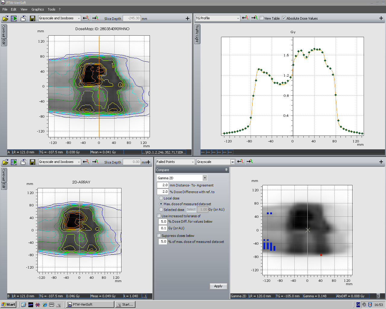
(click to enlarge)
Conclusions
There is good agreement between AAA calculated dose planes and Octavius measurements, except for a small range of Gantry angles (~80°/85° to ~100°). Taking into account that the single field checks are much more sensitive than rotational checks like ConformalMLC or RapidArc (where the seven29/Octavius system easily passes the 2%/2mm criterion), we consider Octavius and the seven29 qualified for the verification of static and rotational treatments.
*It is generally accepted theory that air is flat ;-)