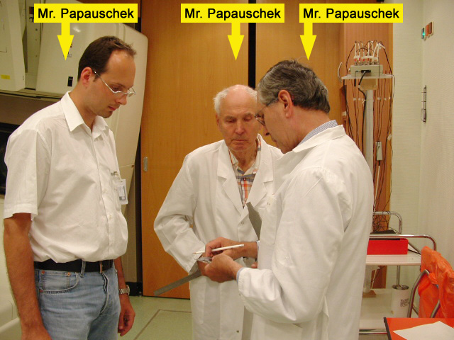
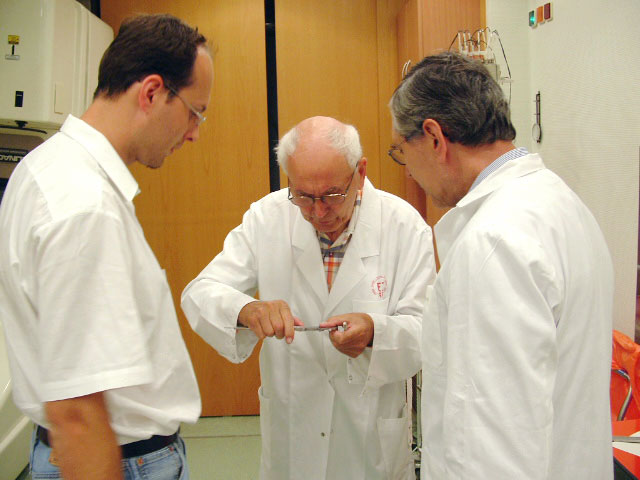
Fig.1: The expert group, consisting of Mr. Papauschek, Mr. Papauschek and Mr. Papauschek, discusses the problem.
Fig.2: A Gantry mounted stage (G-Stage) shall be designed for the PTW 2D-ARRAY. This is a simple task for the expert team.
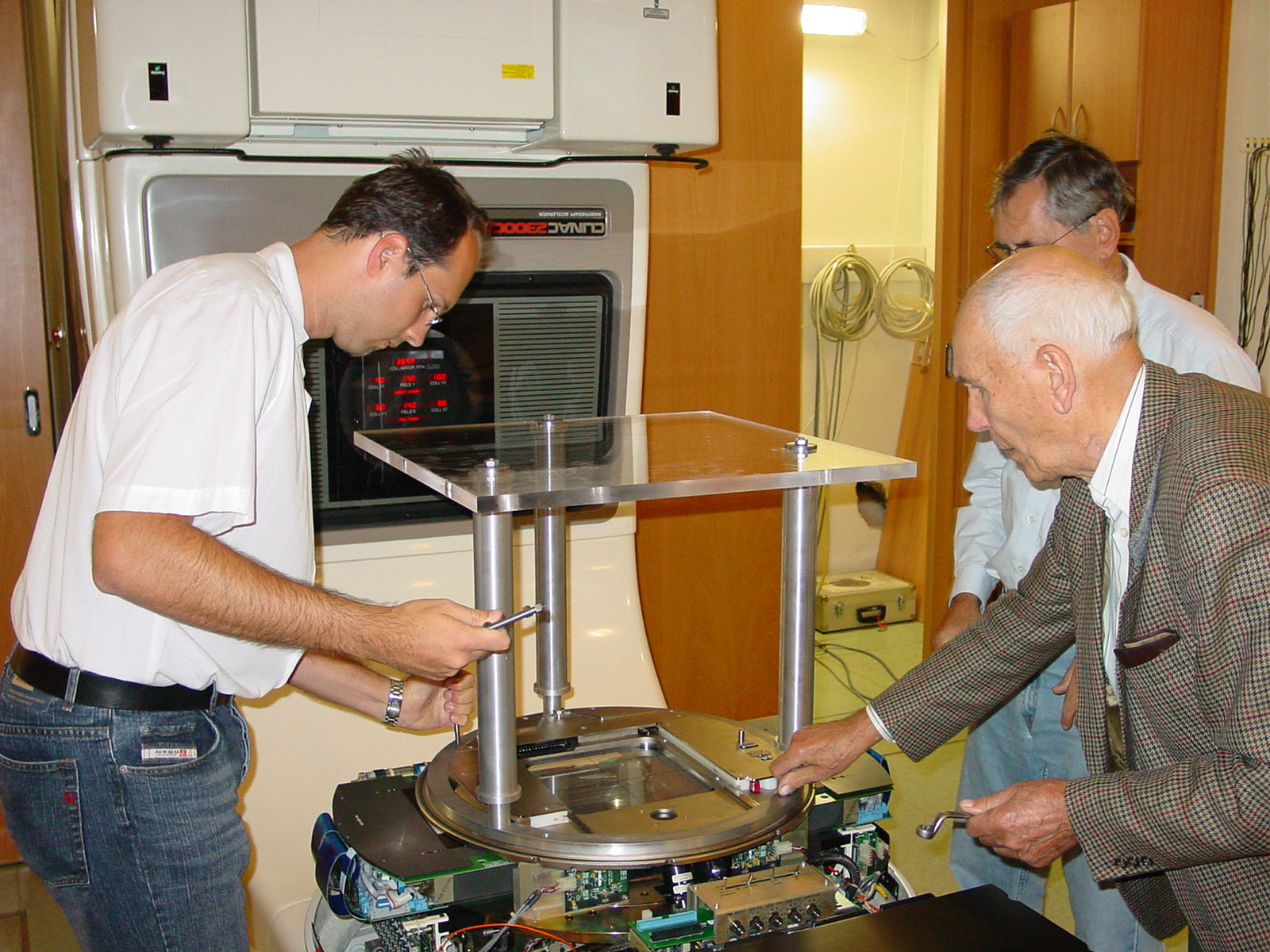
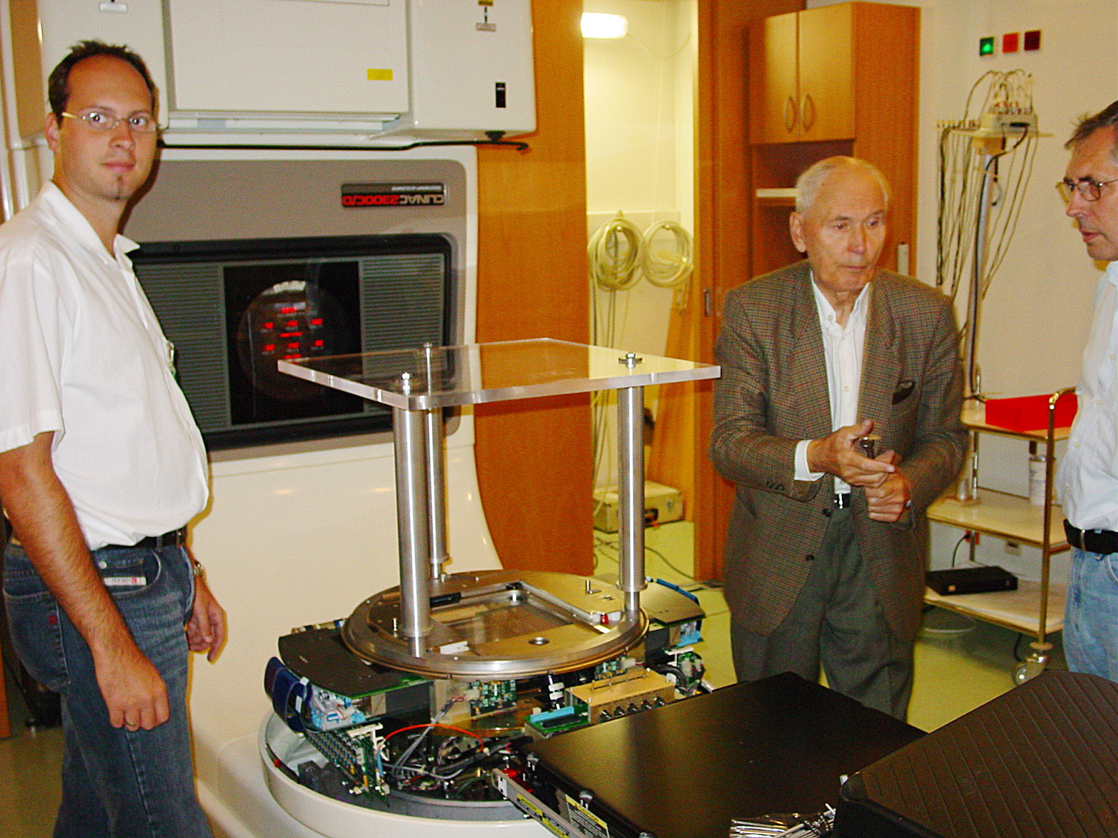
Fig.3: After a few days, the G-Stage is mounted to the collimator head.
Fig.4: The mechanical stability of the assembly has high priority. An aluminum ring is used for docking.
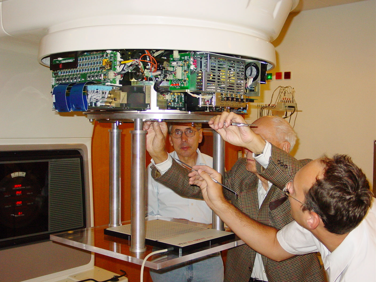
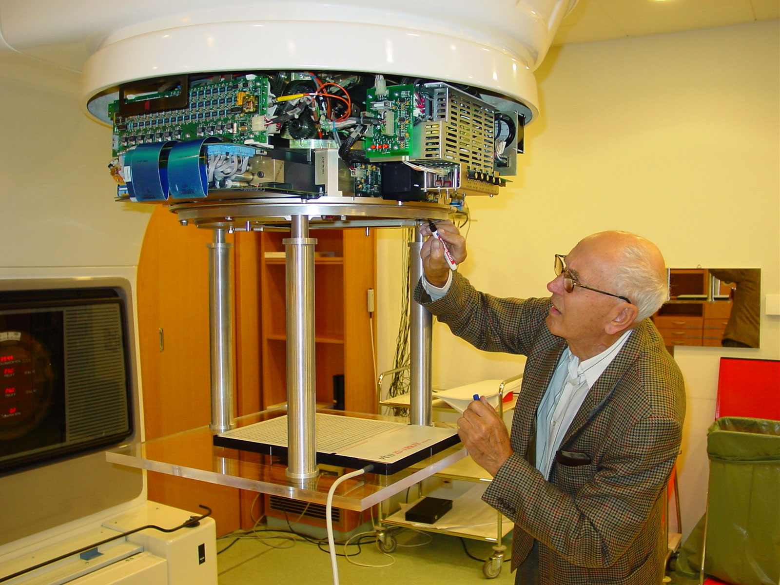
Fig.5: This avoids Varian's Accessory Mount, which is less ideal. The ring is mounted directly to the collimator head.
Fig.6: The ARRAY surface is at SSD100 if 1cm of Solid Water is placed under the ARRAY.
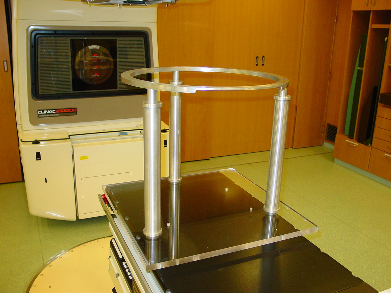
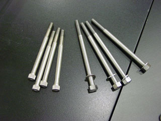
Fig.7: To mount the stage, the Gantry has to be rotated down and 4 screws removed.
Fig.8: The set of screws on the right is used instead of the original set (left).
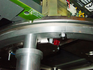
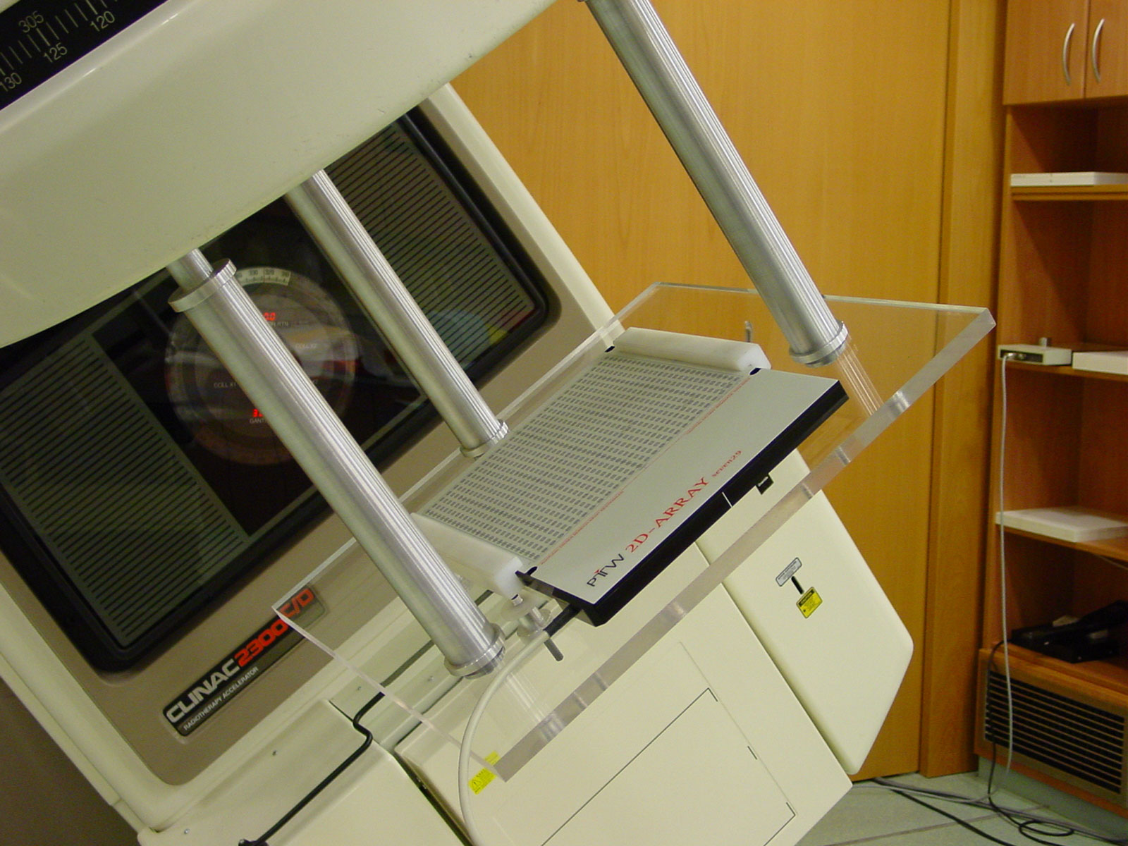
Fig.9: The whole procedure takes only a few minutes. The plastic cover of the collimator may stay in place.
Fig.10: Four more screws and two plastic rails hold the ARRAY in place when the Gantry rotates.
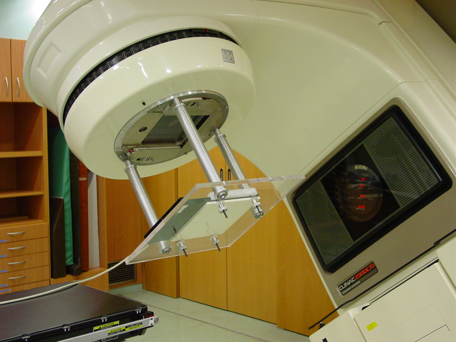
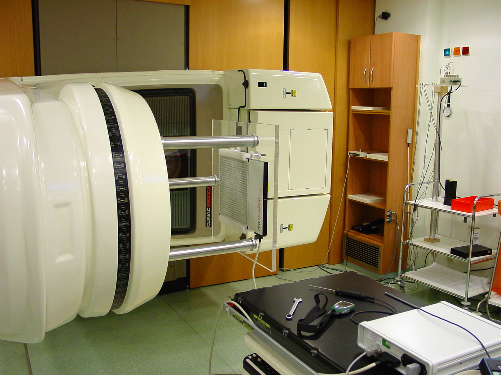
Fig.11: These screws are tightened only gently.
Fig.12: There is no mechanical play in the assembly, only elastic deformation.
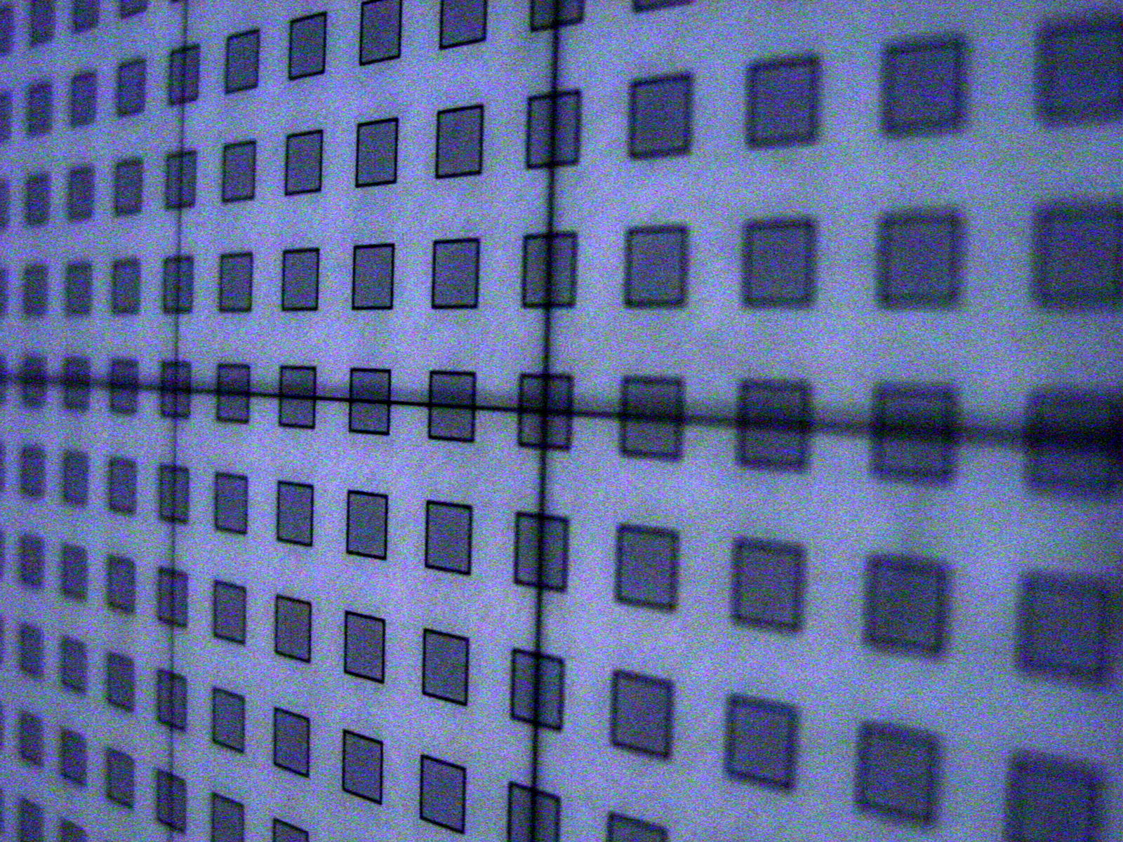
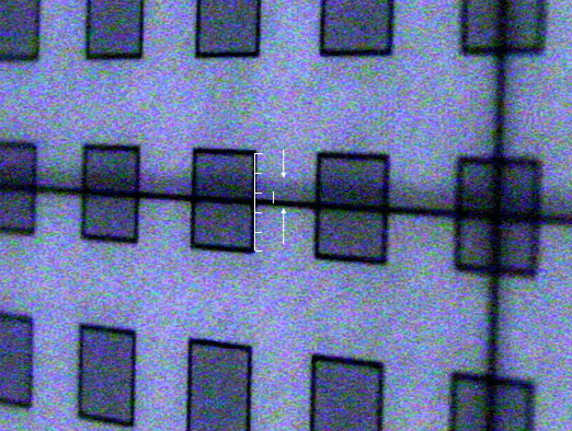
Fig.13: Due to weight, the stage hangs down a little at Gantry 270°, after aligning the ARRAY at gantry 0°.
Fig.14: The chambers are 5x5mm. The displacement is less than 1mm.