Image Quality of CBCT for Patients with Double Hip Prothesis
Sometimes we get asked: "What is the image quality of your Cone Beam CT if the patient has a double hip prothesis?" The surprising answer is that with TrueBeam 2.0, CBCT image quality in such cases is even better than planning CT quality.
The following patient received VMAT treatment of the prostate. For such patients, daily CBCT imaging is our standard procedure, followed by matching and online correction in six degrees of freedom, using the PerfectPitch 6-DoF couchtop.
Session 31
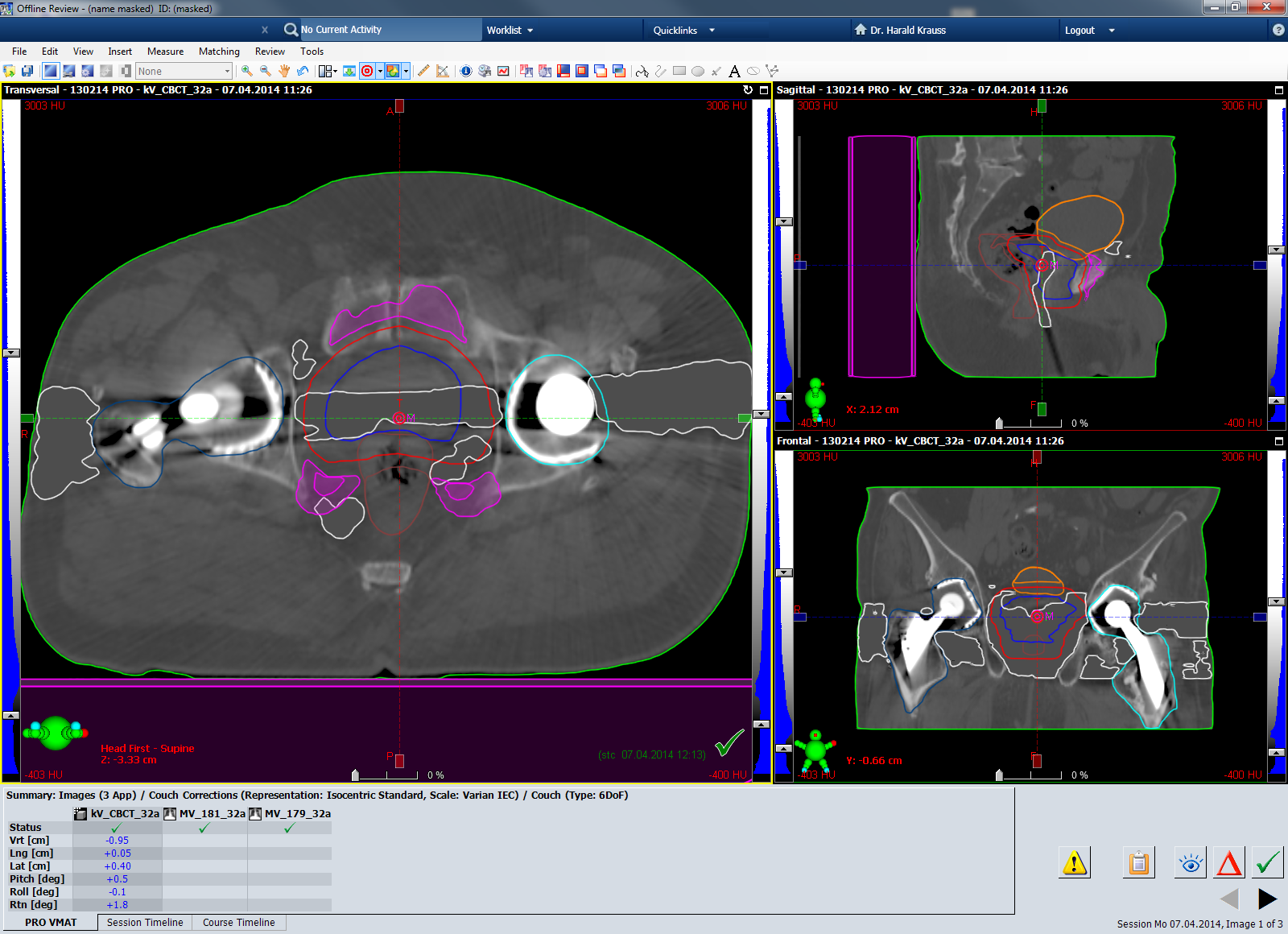
The first image shows the Cone Beam CT acquired during session 31. The screenshot also shows the Pitch and Roll values after online matching and correction:
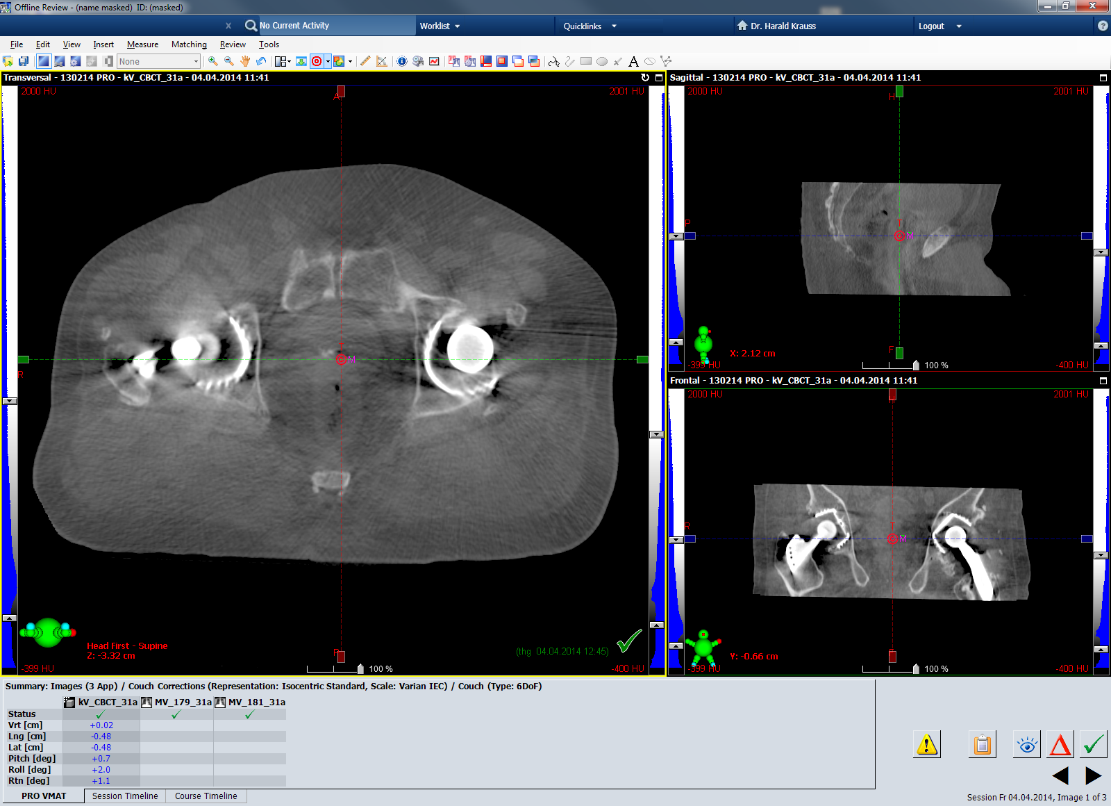
(Fig 1: TrueBeam CBCT, Session 31.)
The next screenshot shows the planning CT in the same three planes as the CBCT, with the same window/levelling. The beam hardening artefacts between the two metal implants are much stronger than on the CBCT image:
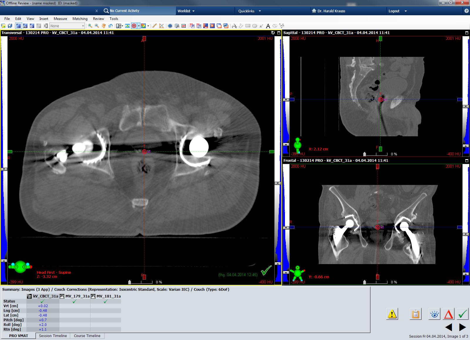
(Fig 2: Planning CT showing isocenter planes of session 31.)
Session 32
This is the CBCT of the next day (session 32):
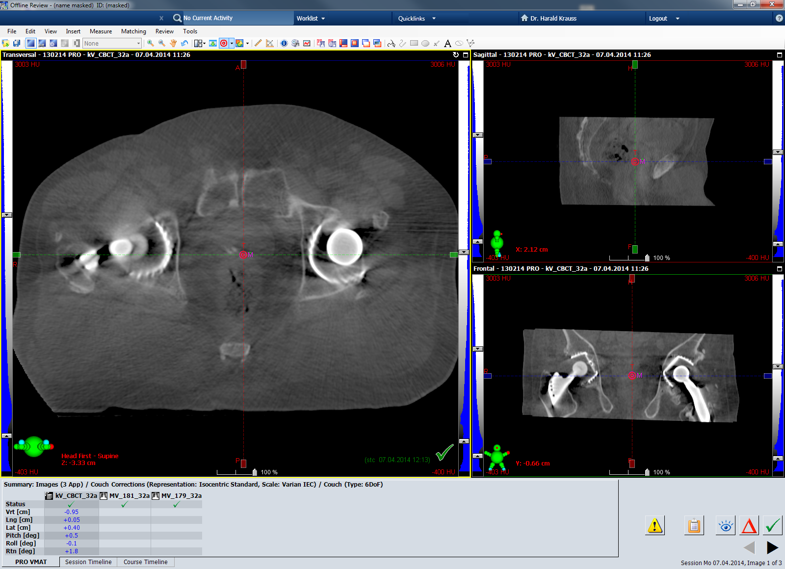
(Fig 3: TrueBeam CBCT, Session 32.)
Window/levelling here was set to (-400 HU to +3000 HU). Here is the planning CT in the same planes, again with the same window/level setting:
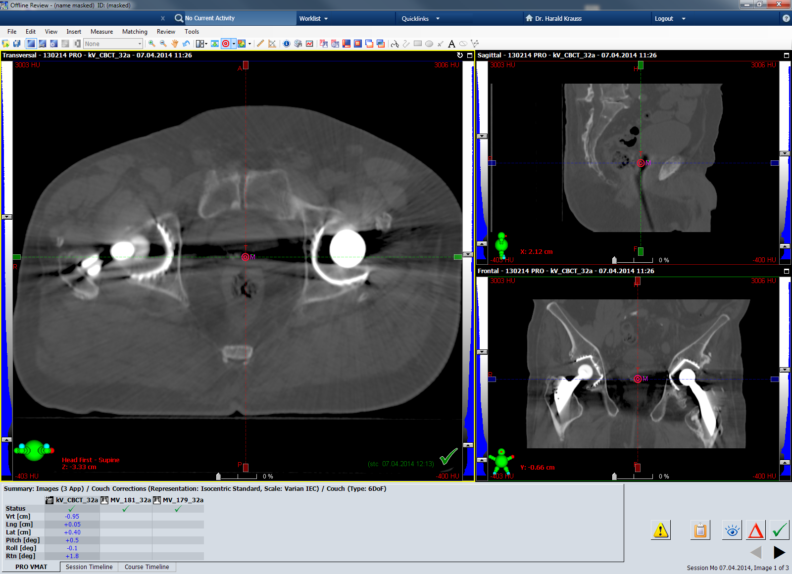
(Fig 4: Planning CT showing isocenter planes of session 32.)
Dose Planning
To reduce the potential impact of the planning CT's beam hardening artefacts on dose calculation, dummy structures are created in Eclipse and filled with 0 HU (water). On the next screenshot, these dummy structures are shown in light grey:
(Fig 5: Planning CT in isocenter planes of session 32. Dummy structures filled with 0 HU are light grey.)
If confidence in the dose calculation algorithm is limited, avoidance sectors can be created in VMAT optimization. The plan we actually selected for treatment of this patient contained two such avoidance sectors. This way, the treatment beam was prevented from penetrating the metal implants during VMAT delivery. The avoidance sectors are visible in the 3D model in the upper right corner of the following screenshot. The ring of red bullets around the patient are the RapidArc control points - they are small red dots if dose rate is zero:
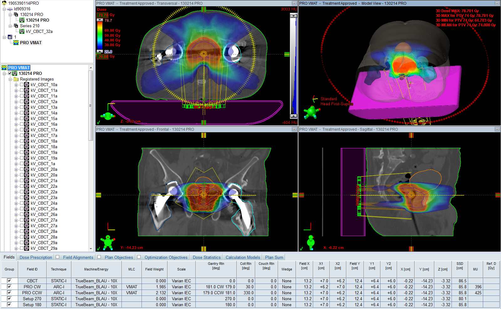
(Fig 6: Actually delivered 10X treatment plan with two avoidance sectors.)
Update, January 2015: Our current practice is that whenever metal implants are in the beam, Acuros XB is used instead of AAA. Acuros XB has demonstrated to provide accurate results behind titanium. Therefore, we now perform VMAT optimization without any avoidance sectors. Image artefacts, however, have to be corrected as described.