...or rather "Challenges!"
The first thing I noticed when I evaluated some DICOM images acquired with the aS500 was that the beam profiles seemed to "hang" towards the Gantry (Fig.1).
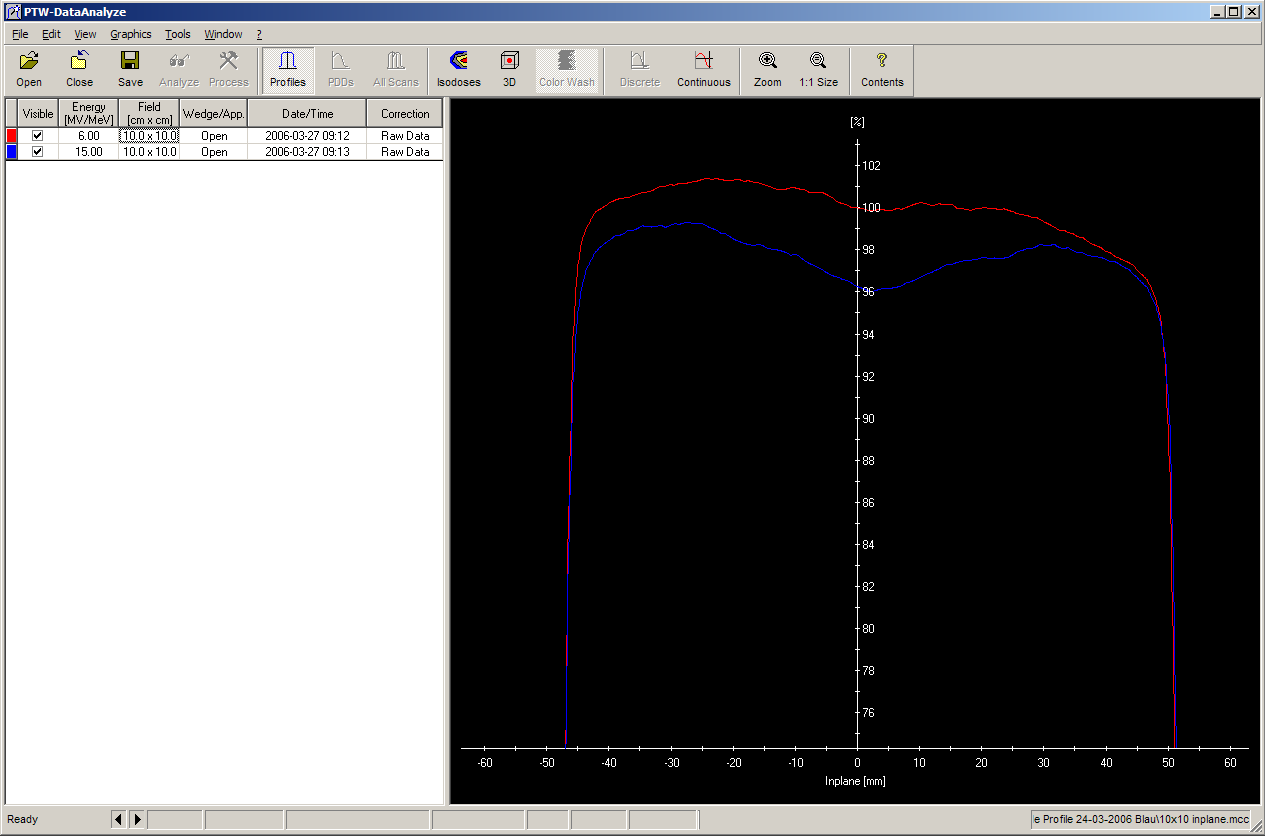
Everybody was alarmed because we first thought the beam was really that asymmetric! But water phantom measurements quickly revealed that the true beam symmetry was nearly perfect. This is valid for all screenshots shown on this page: the real beam was always good ...
So the effect was
probably originating from the image acquisition system. This was also
confirmed when the images of the two identical linacs were compared:
they showed the same effect.
The asymmetry is a little stronger for 6MV than for 15MV. In Crossplane
direction, symmetry is ok. The effect depends on field size. For 25x25,
or 27x36 (the calibration field size), the inplane symmetry is much better,
but for smaller field sizes ... see Fig.2 and 3, comparing three 6MV
inplane profiles. Gantry is on the right for all inplane profiles shown.
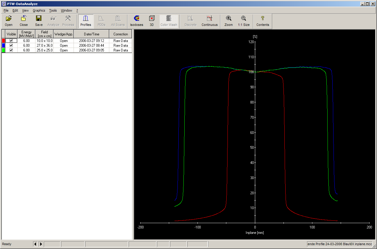
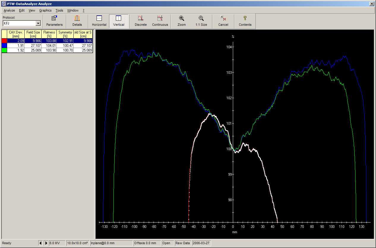
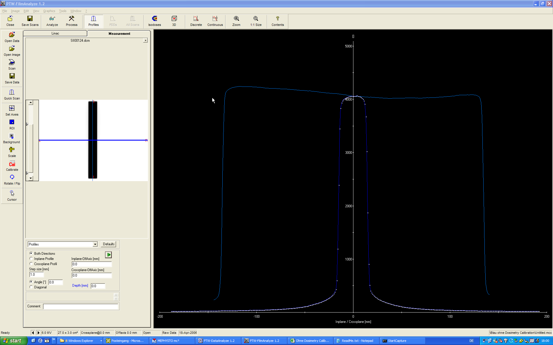
Fig.4: A narrow and long field (see insert on the left). The imager was calibrated without beam profile correction. The plateau therefore should be perfectly flat.
Fig.5 shows the plateau region of Fig.4 zoomed. The high energy image looks similar (not shown).
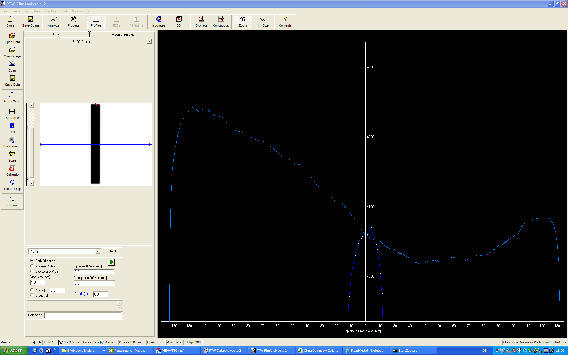
Fig.5: Zoomed plateau in the 6MV image.
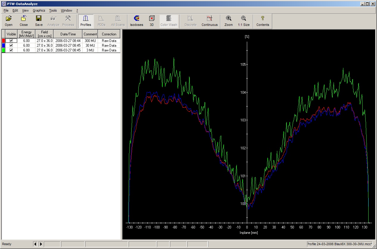
Fig.6: Inplane profiles of a 6 MV, 27x36 cm field taken at 3 (green), 30 (blue) and 300 MU (red).
The "hanging profiles" problem is one of the things Varian needs to solve. The situation is identical for IDU11 and IDU20.
Nevertheless, the Varian Portal Dosimetry system is very useful and is routinely used for IMRT verification in our department. To reduce the inplane effect, it often helps to rotate the collimator to 90°, if the fields are longer than wide.
The following table sums up some general advantages and disadvantages of the Portal Dosimetry system:
| Pros | Cons |
|---|---|
Very fast. No Phantom setup required |
Not measuring dose, rather fluence |
Controlled by ARIA. No setup error possible |
TPS uses different algorithms for 3D-dose and PDIP |
Documented by ARIA. No lost data |
No cumulation of subfields during large-field IMRT possible |
High resolution digital image (512x384 or 1024x768) |
No plan verification, only field verification |
40x30cm measurement area |
... |