Example case #1: a 52 year old male patient with an an oropharynx carcinoma, which was treated with the Simultaneously Integrated Boost (SIB) technique. The target volumes were the PTV (60 Gy), the SIB-volume (63 Gy) and the Supraclavicular Lymph Nodes (50 Gy). The Beam Angle Optimizer of Eclipse 8.1 proposed 6 IMRT fields. The Supraclavicular region was treated with a non-IMRT static MLC field, with the same isocenter as the IMRT plan (asymmetric match).
Due to the size of the IMRT volumes, three out of the six IMRT fields were split into two carriage groups by the system. 3D-Dose was calculated with the AAA 8.1.14.
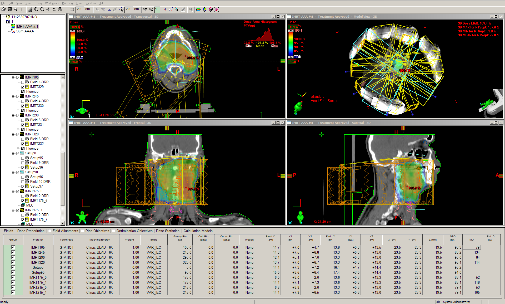
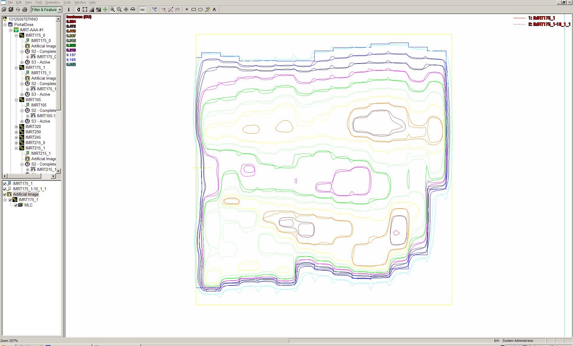
Dose of the IMRT plan showing the SIB volume inside the larger PTV volume (click to show full planning area).
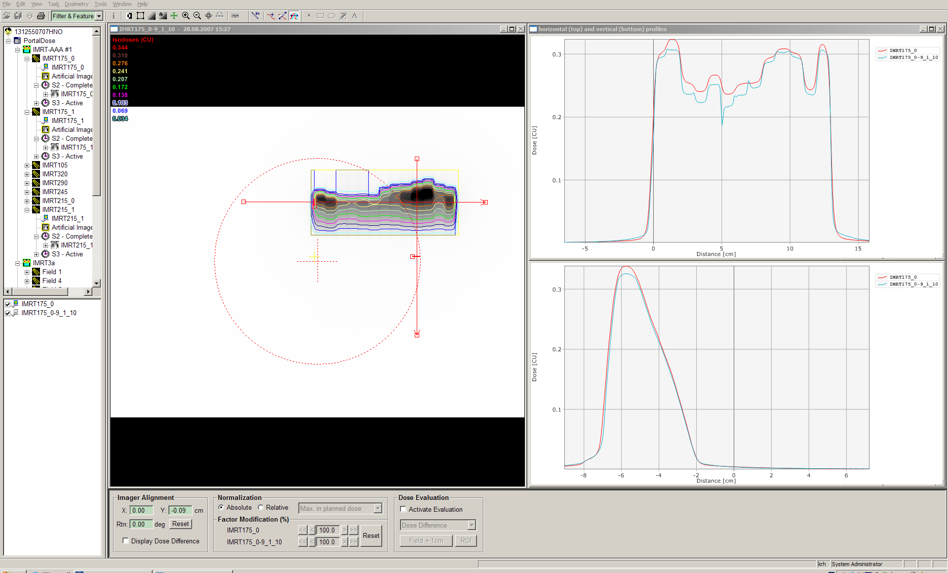
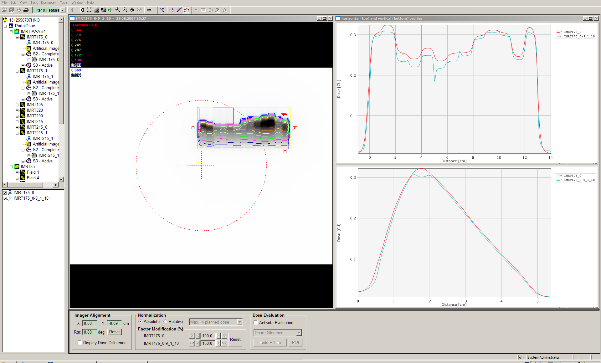
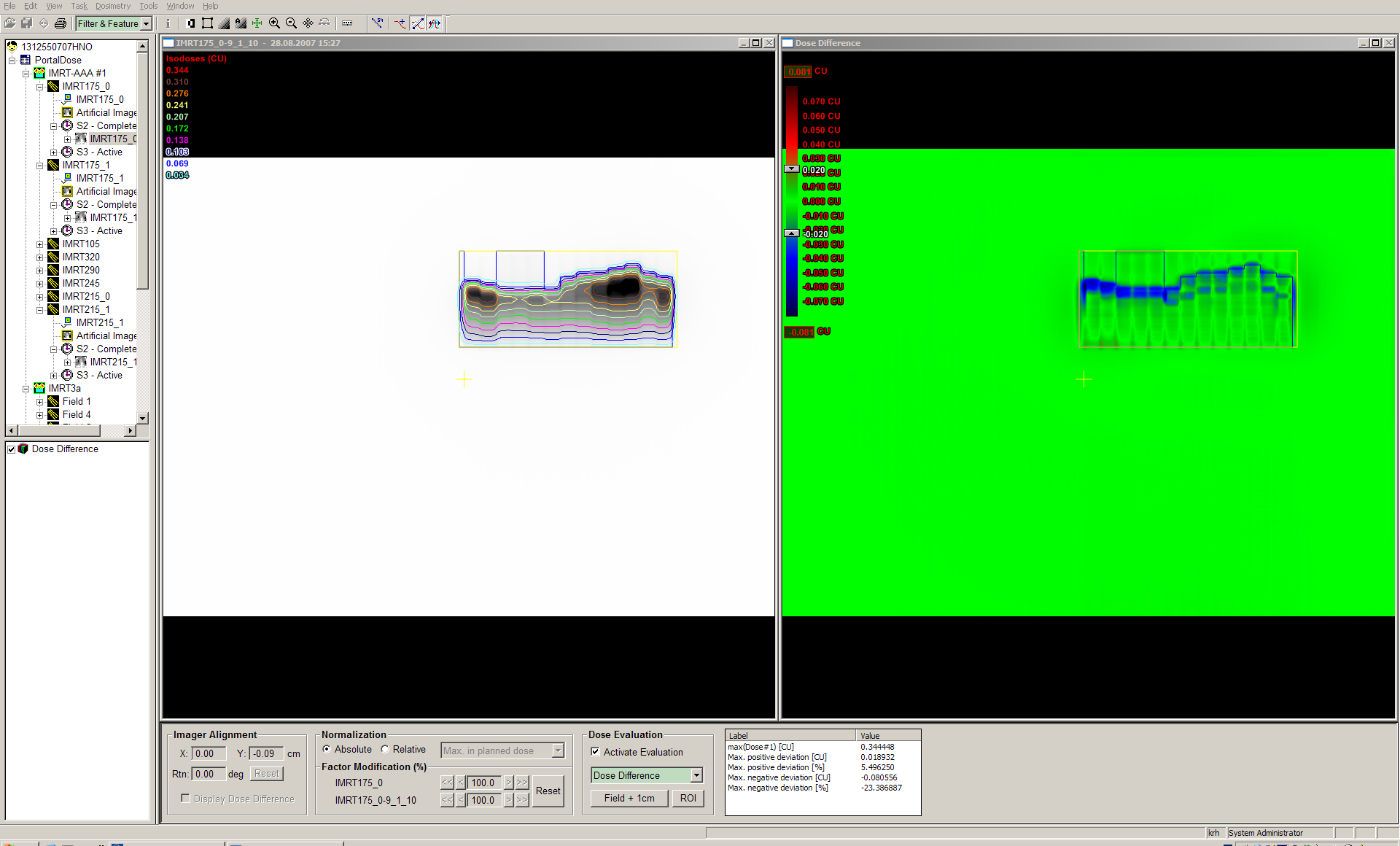
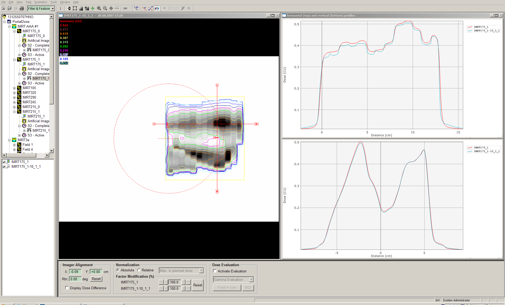
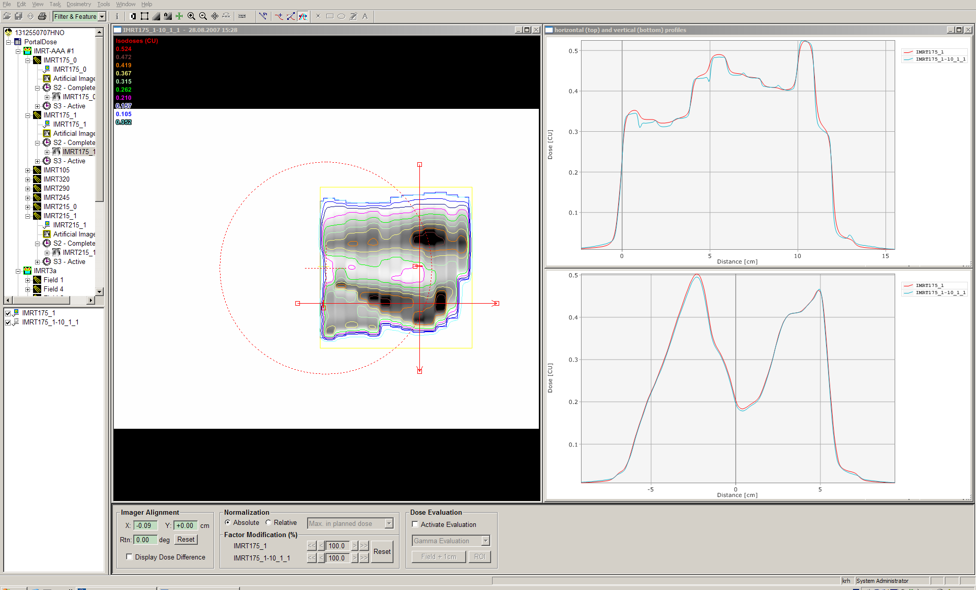
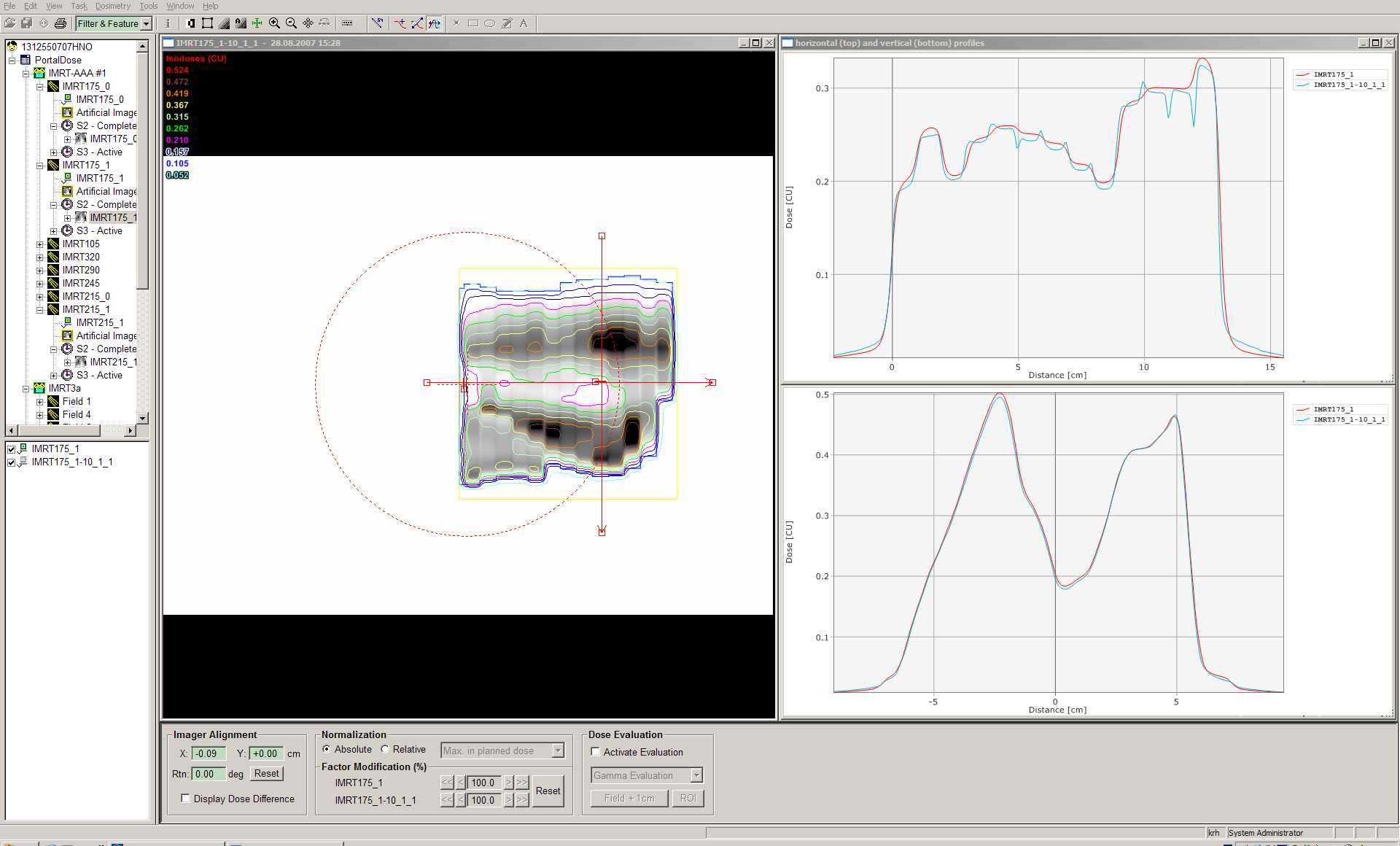
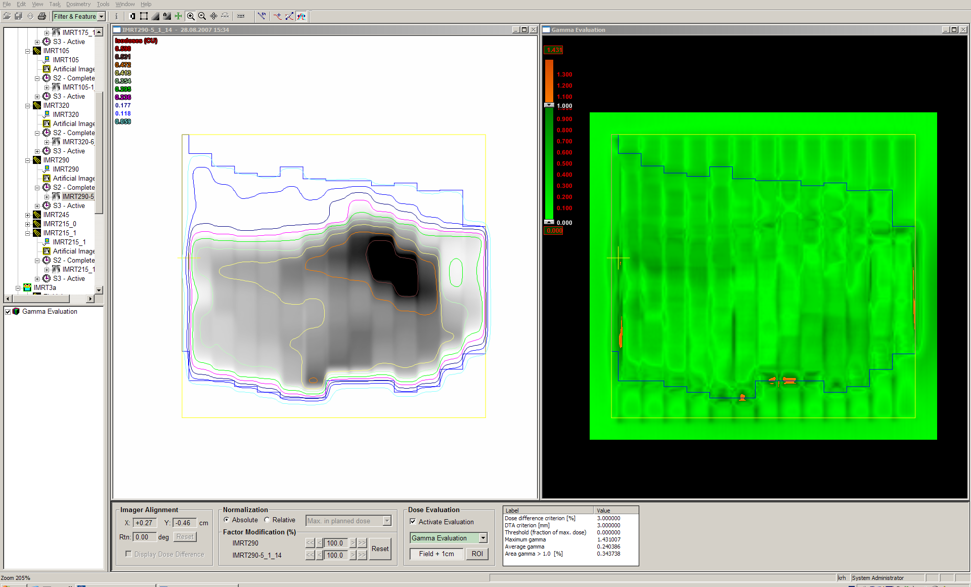
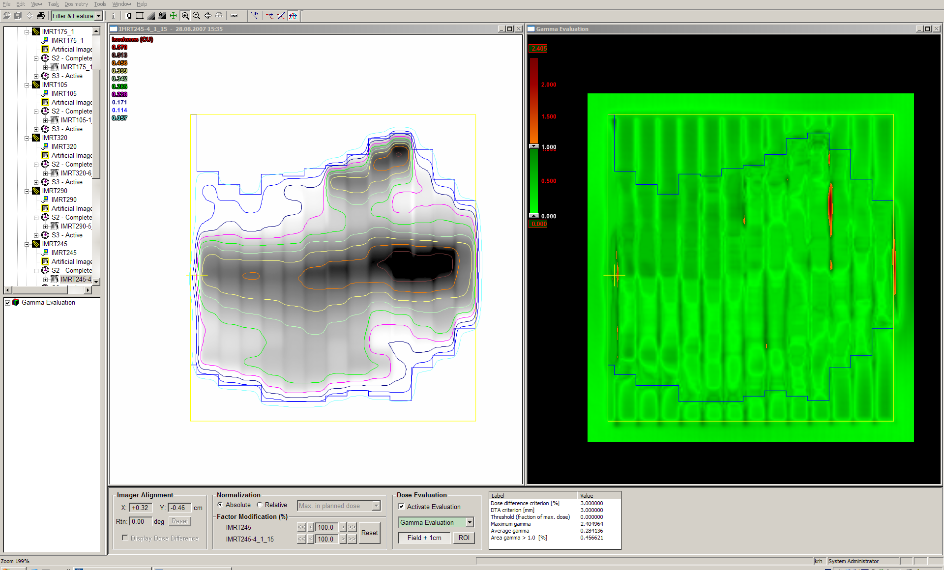
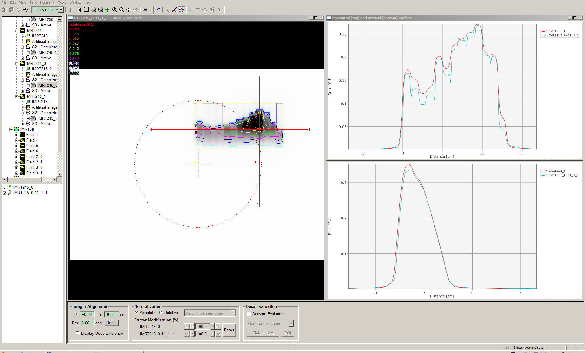
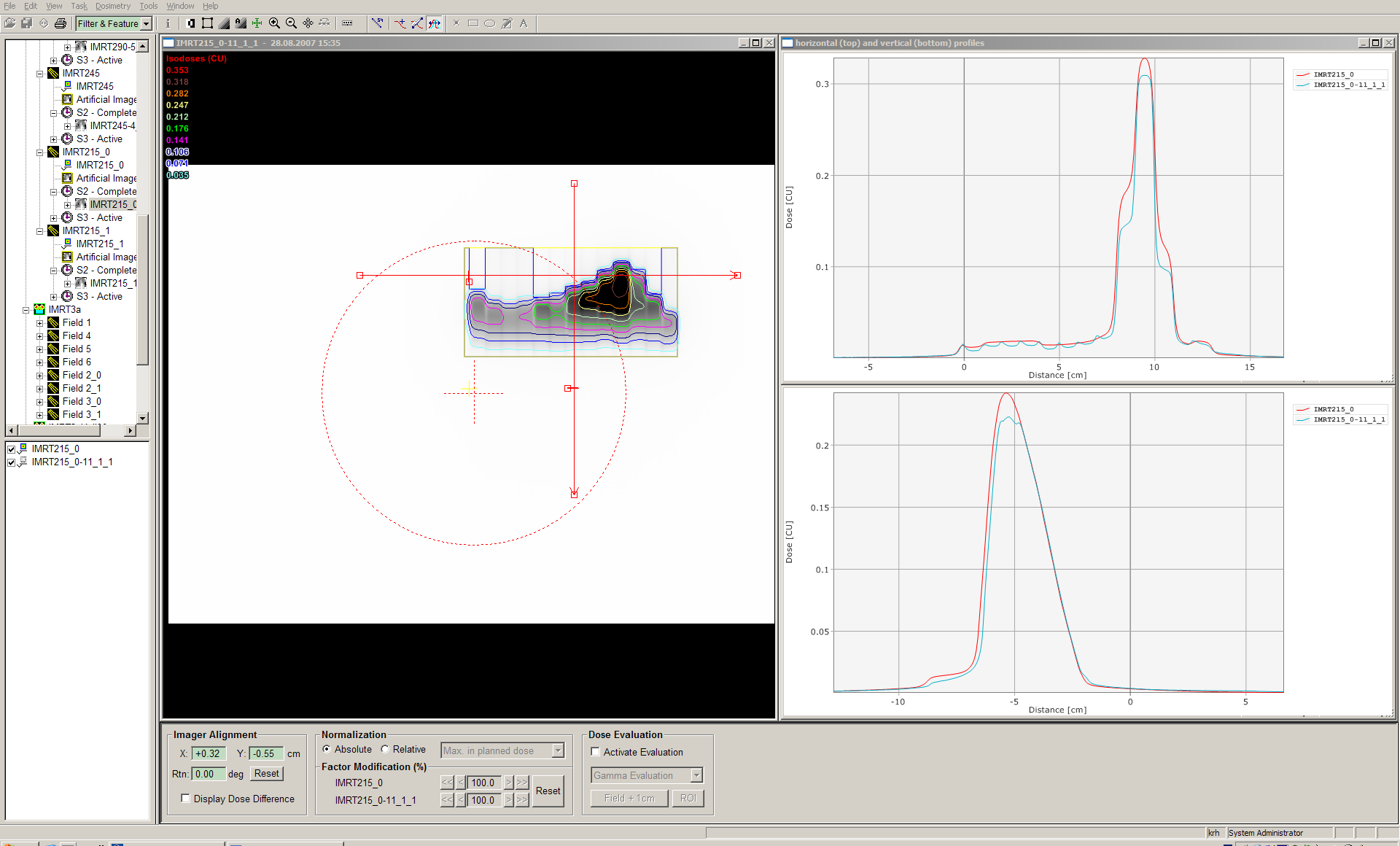
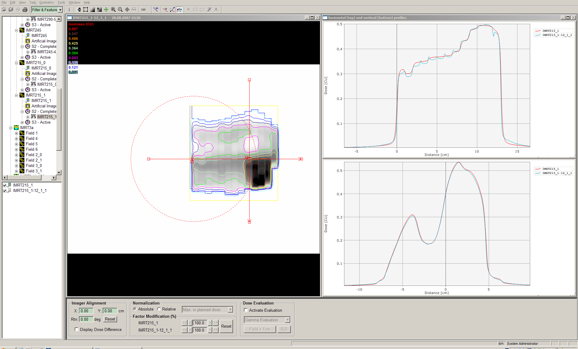
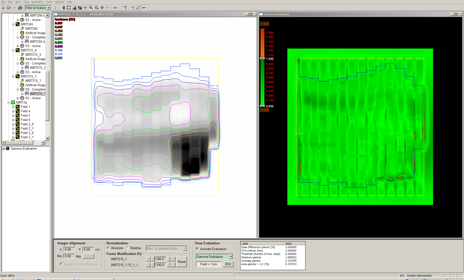
The IMRT plan was verified with Portal Dosimetry.
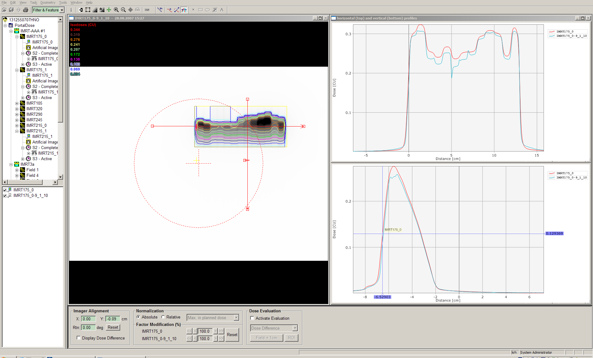
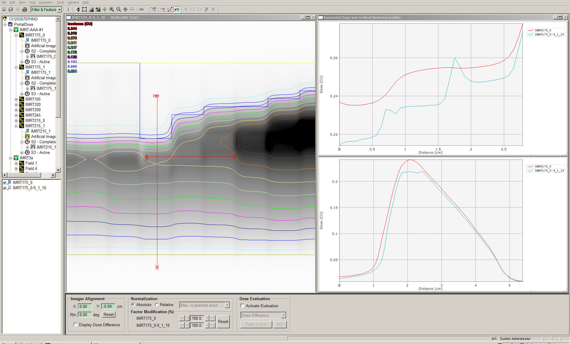
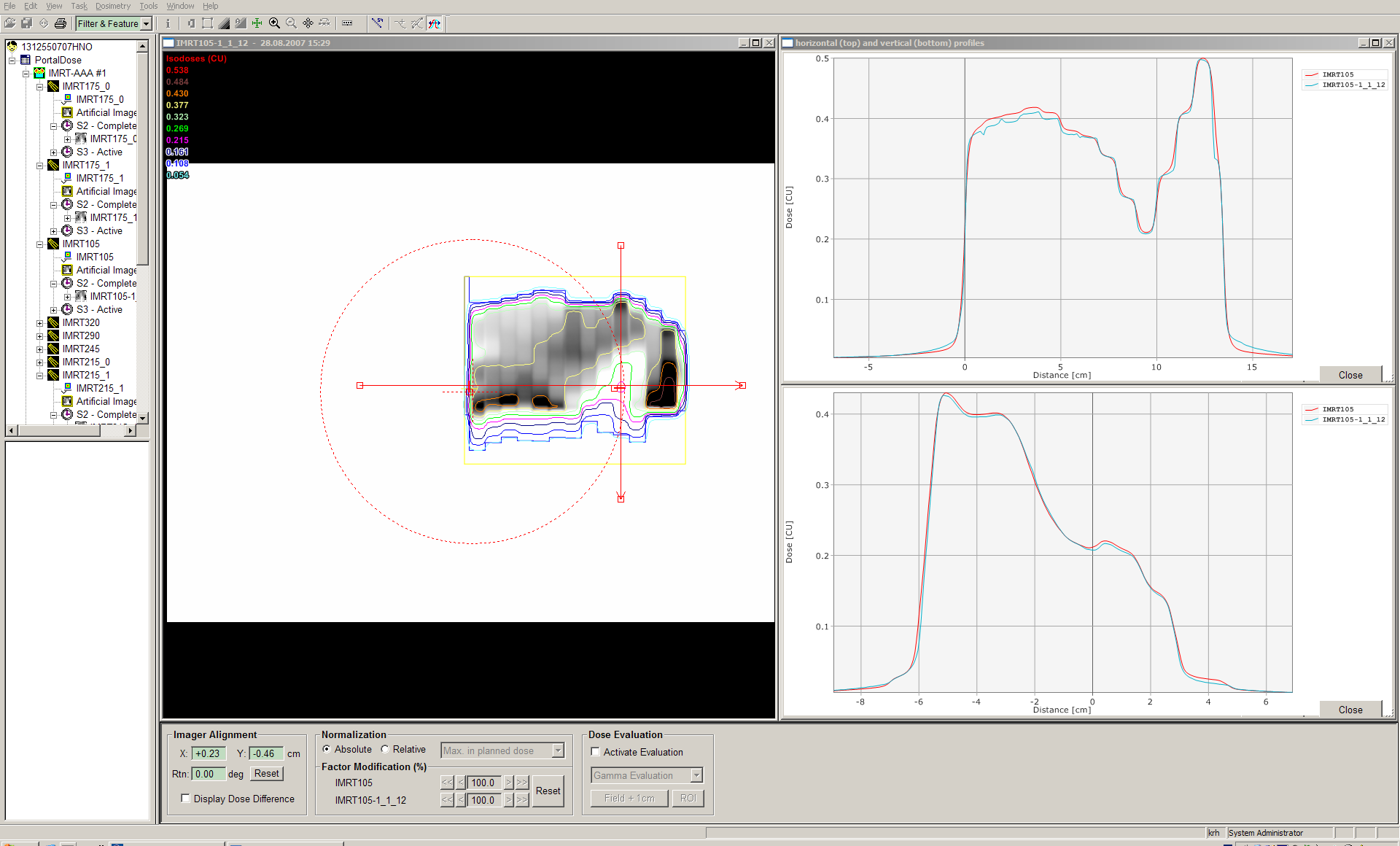
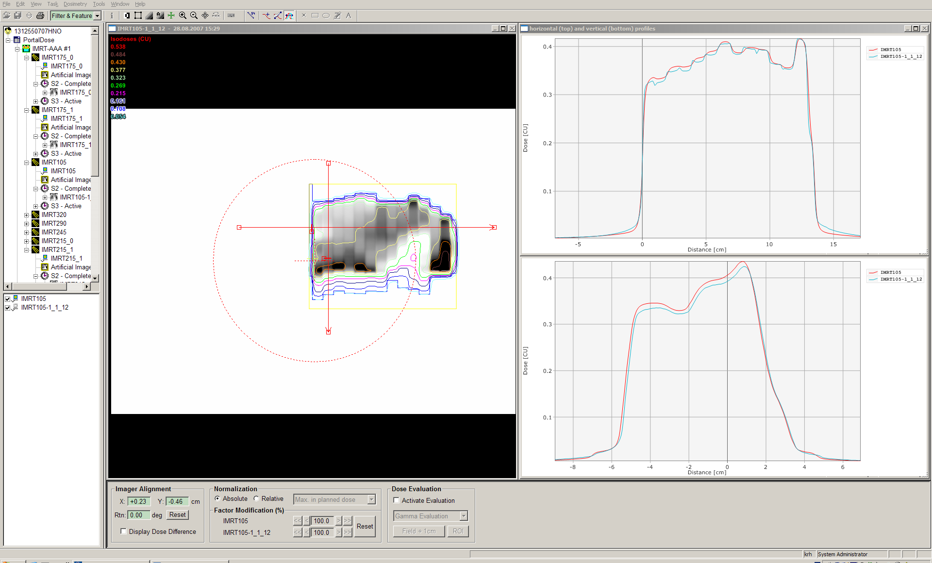
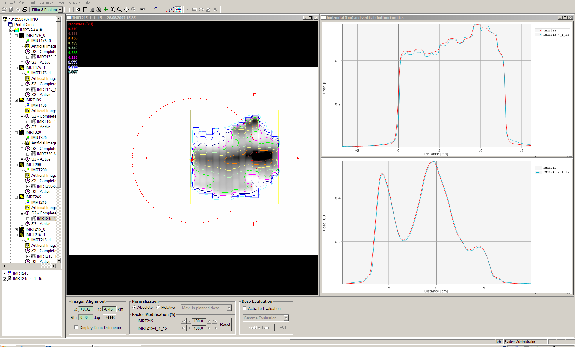
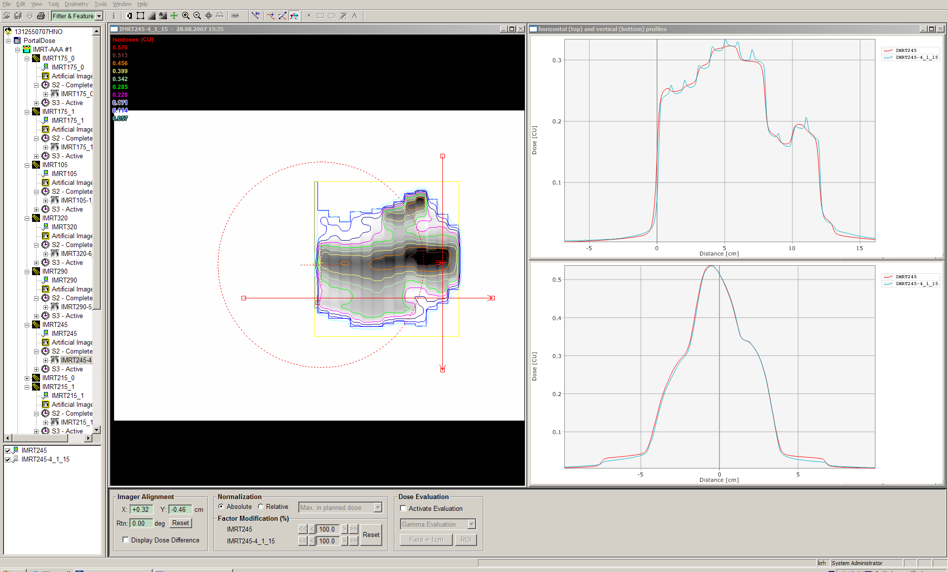
The screenshots show good agreement, except for
IMRT175_0 and IMRT215_0 (1st carriage group of the respective fields). The difference in the inplane profiles (blue: measured image, read: predicted image) could have several reasons: maybe the image aquisition started a little too late, therefore missing some fluence; the hanging profiles problem, because the affected region is in the upper half of the detector; a Leaf Motion Calculator (LMC) problem for multiple carriage groups; and many more...
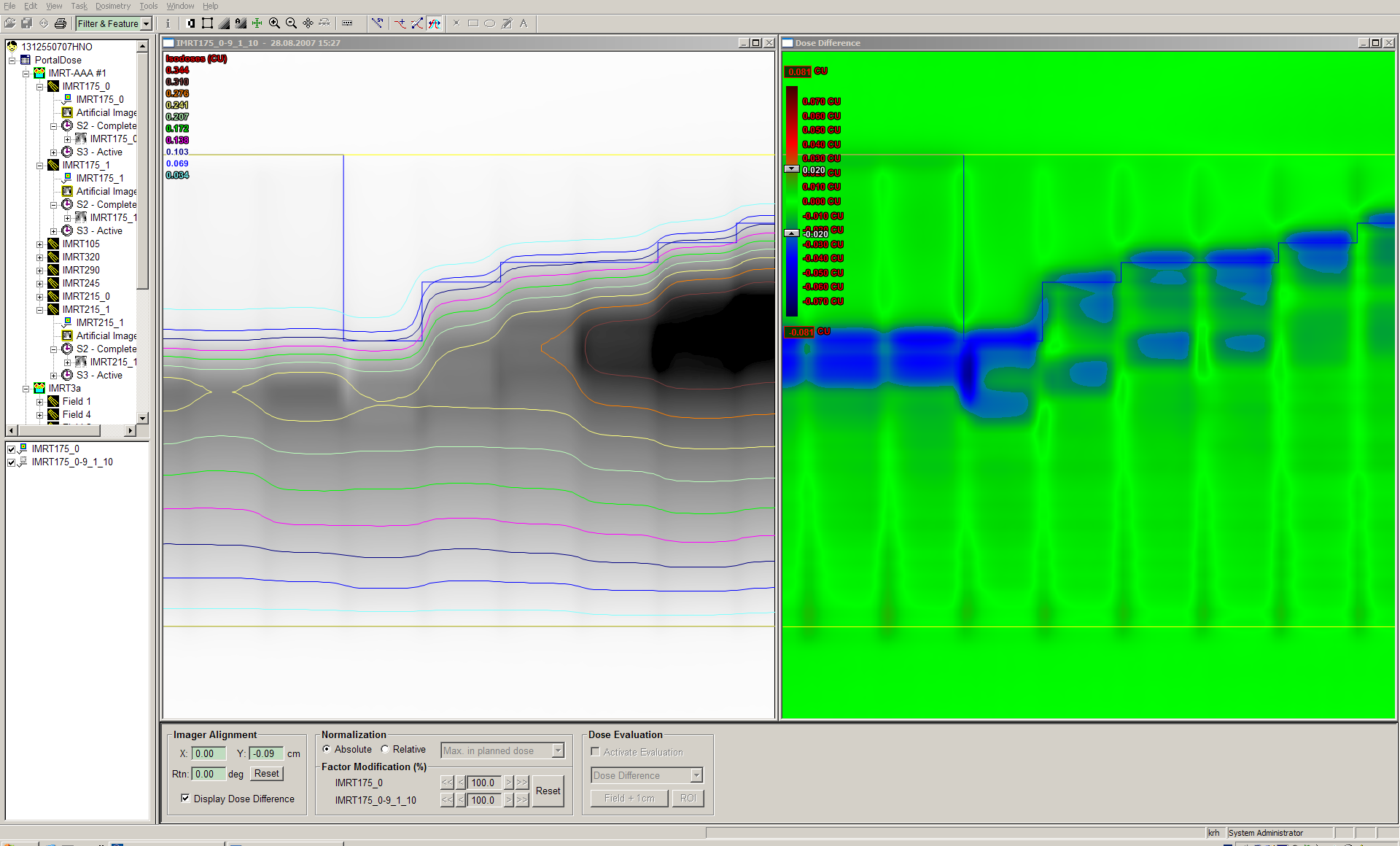
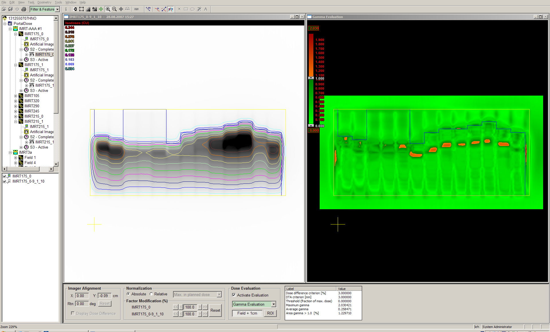
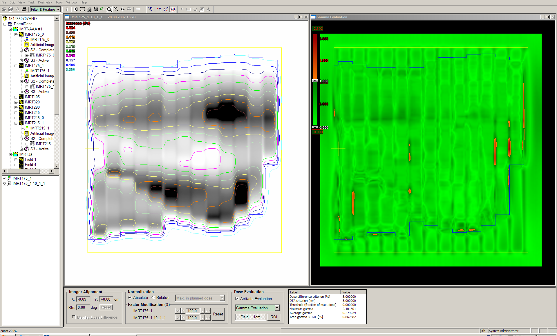
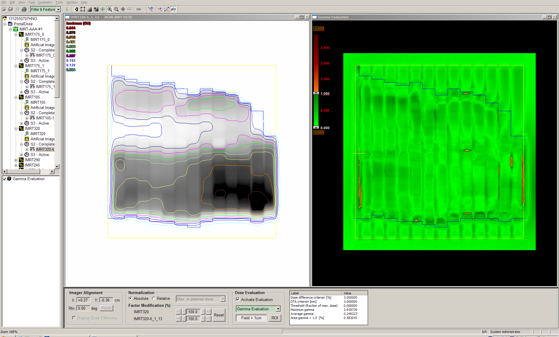
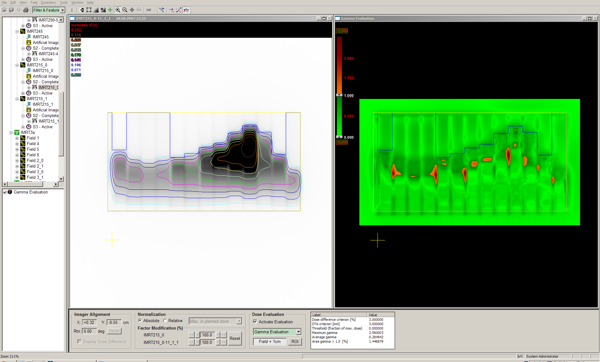
We use the 3%/3mm Gamma index criterium and evaluate the field plus 1 cm margin. In this region of interest, the fraction of failing pixels (drawn in red) is usually around 1% or less. Tongue-and-groove effect is the main cause of failing areas. There is no hard rule when to reject the plan. In case of unacceptable agreement (never happened) we would re-verify the plan with the 2D-ARRAY, our gold standard.
 |
 |
 |
 |
 |
 |
 |
 |
 |
 |
 |
 |
 |
 |
 |
 |
 |
 |
 |
 |
 |
 |
 |
 |
 |