Before the imager can be used for Portal Dosimetry, it has to be calibrated. In contrast to the detector calibration procedure described in our Poor Man's Approach to Portal Dosimetry, Varian recommends to calibrate the detector as close to the focus as possible (R-Arm: 105 cm, Exact Arm: 100 cm).
The calibration is a two-step process:
- Dark-Field and Flood-Field Calibration of all IMRT scanning modes that shall be used for Portal Dosimetry, e.g. 6 MV, 300 MU/min; 15 MV, 300 MU/min. It provides the basic image quality (uniformity etc.) needed for 2D-measurements, leaving the absolute pixel values untouched.
- Dose Calibration with a reference field (10x10 cm) and the detector in the reference distance. This step calibrates the absolute pixel values (Calibrated Units).
The steps are independent in terms of frequency of recalibation. It may happe that you feel the image quality of the integrated images could be better. Then it is usually sufficient to redo the Dark-Field and Flood-Field Calibration.
Dark-Field and Flood-Field Calibration
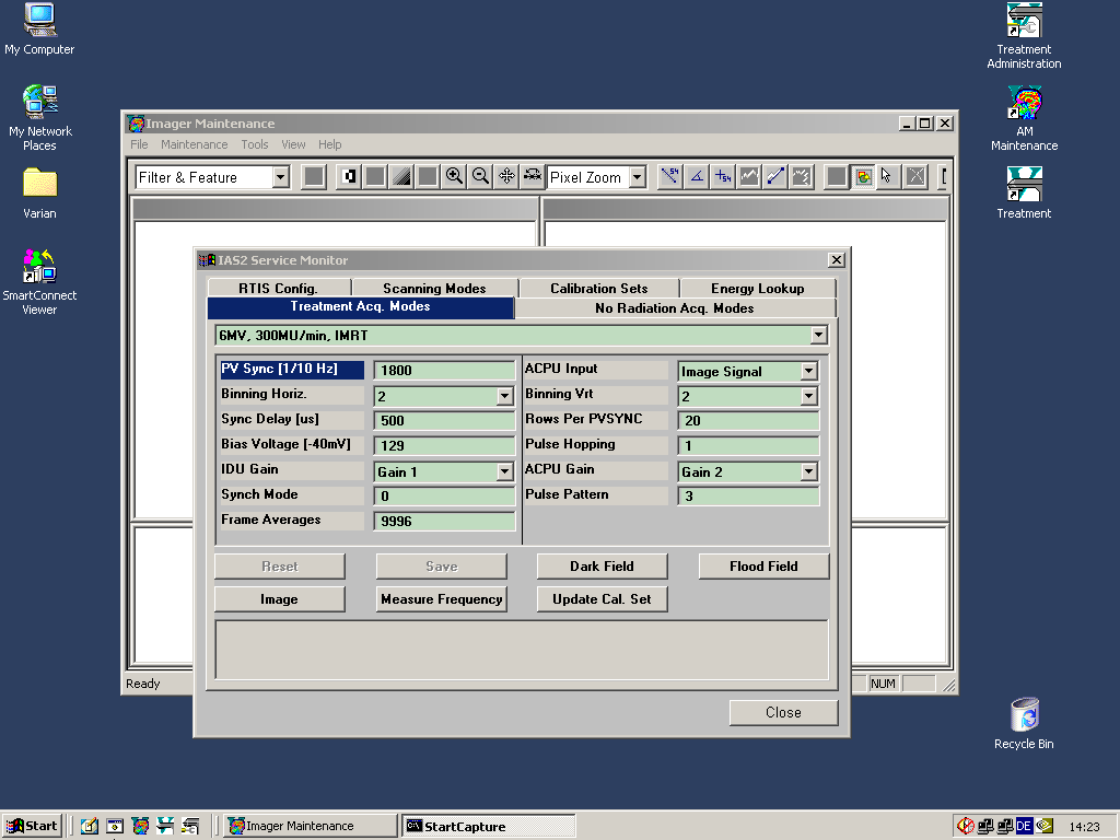
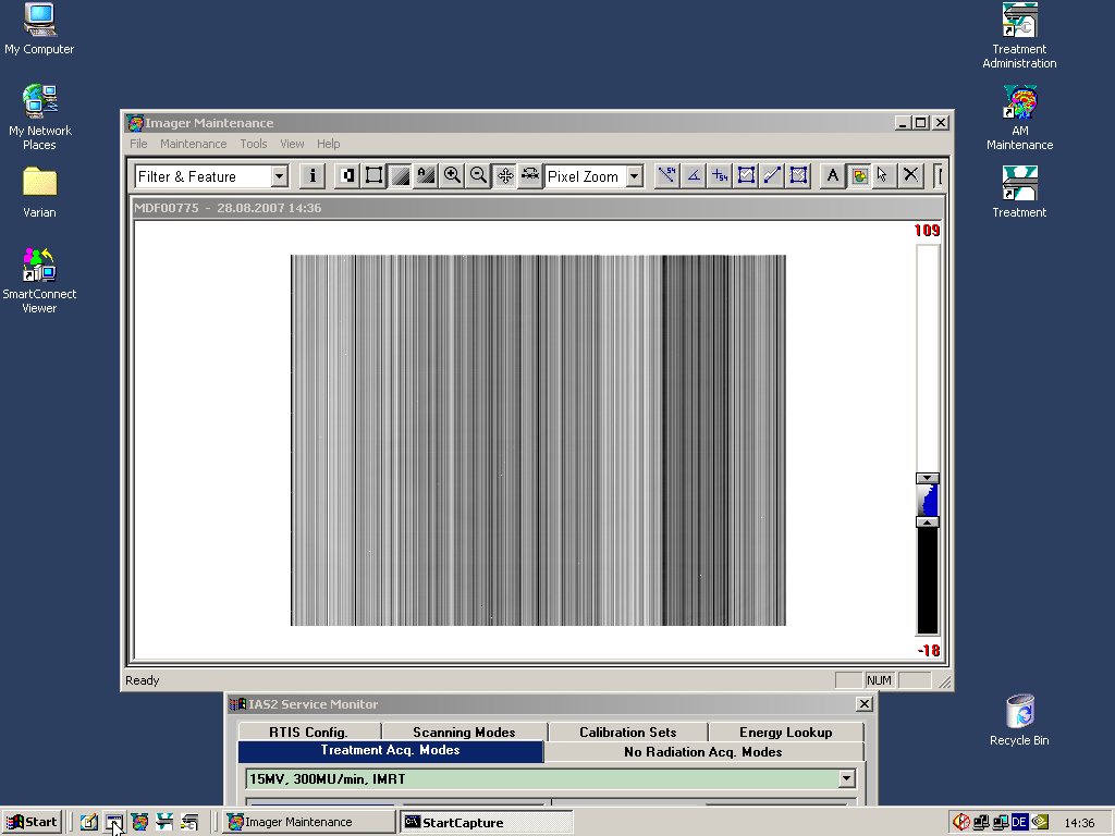
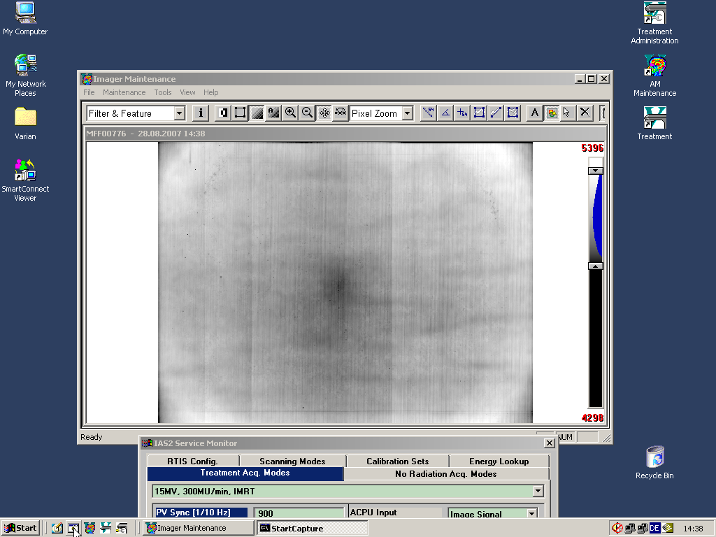
This is done in Maintenance > Service Monitor ... because the IMRT scanning modes are independent of the normal imaging modes.
For the flood field calibration we use the jaw setting X=39.0 cm, Y1=15.5 cm, Y2=14.5 cm at 105 cm.
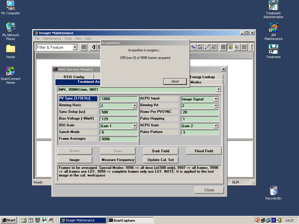
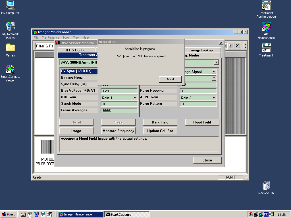
Since the maximum number of frames is something like 9996, the dark field and flood field acquisitions have to be stopped manually after a certain number of frames.
So the question is: How many frames? Varian recommends to acquire at least 50 frames for both dark field and flood field. We use at least 500 frames.
Fig.1 shows an image acquired with 300 frames and the same maximum field size as during calibration after the flood field calibration had been performed with 300 frames (6 MV, 300 MU/min). There is still a horizontal stripe visible, which leads to a 0.5% step in the inplane profile. The stripe is always at the same position, independend on the number of frames chosen for the image acquisition. Therefore, it has to originate from the flood field calibration image.
IMRT settings 6MV
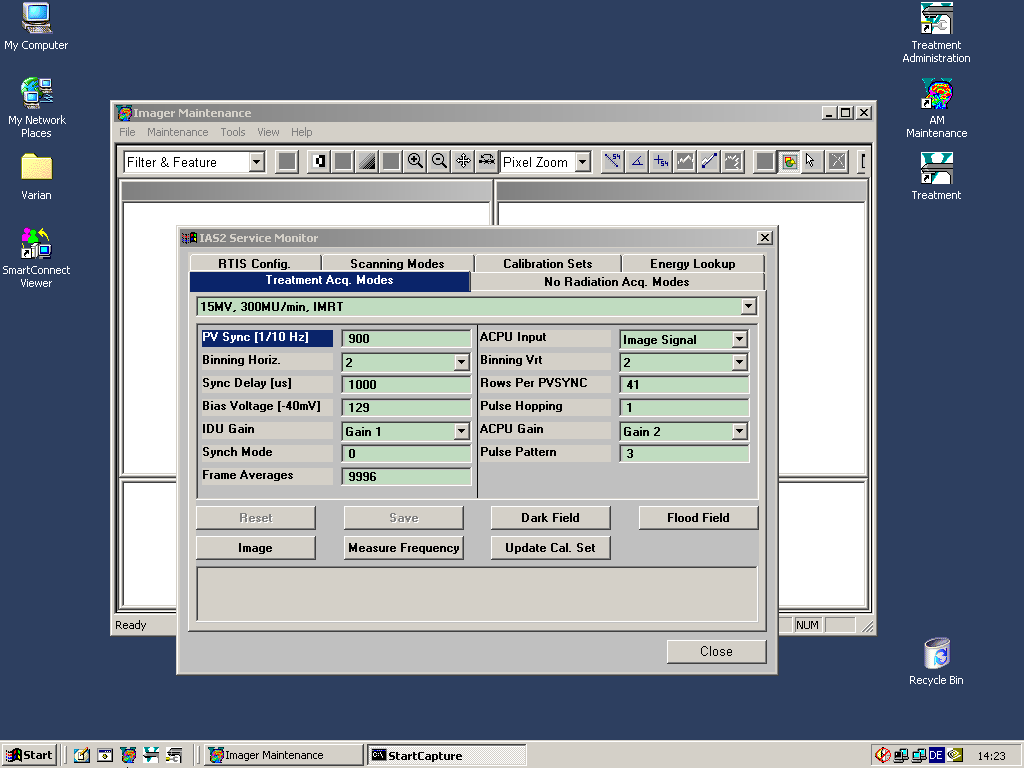
IMRT settings 15MV
acquiring dark field 6MV
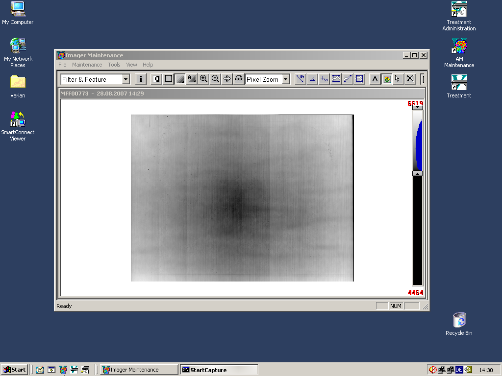
acquiring flood field 6MV
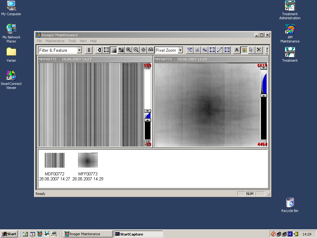
display df and ff
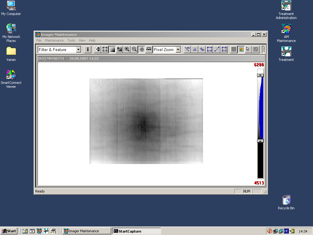
X2 field size too small
field size better
dark field 15MV
flood field 15MV
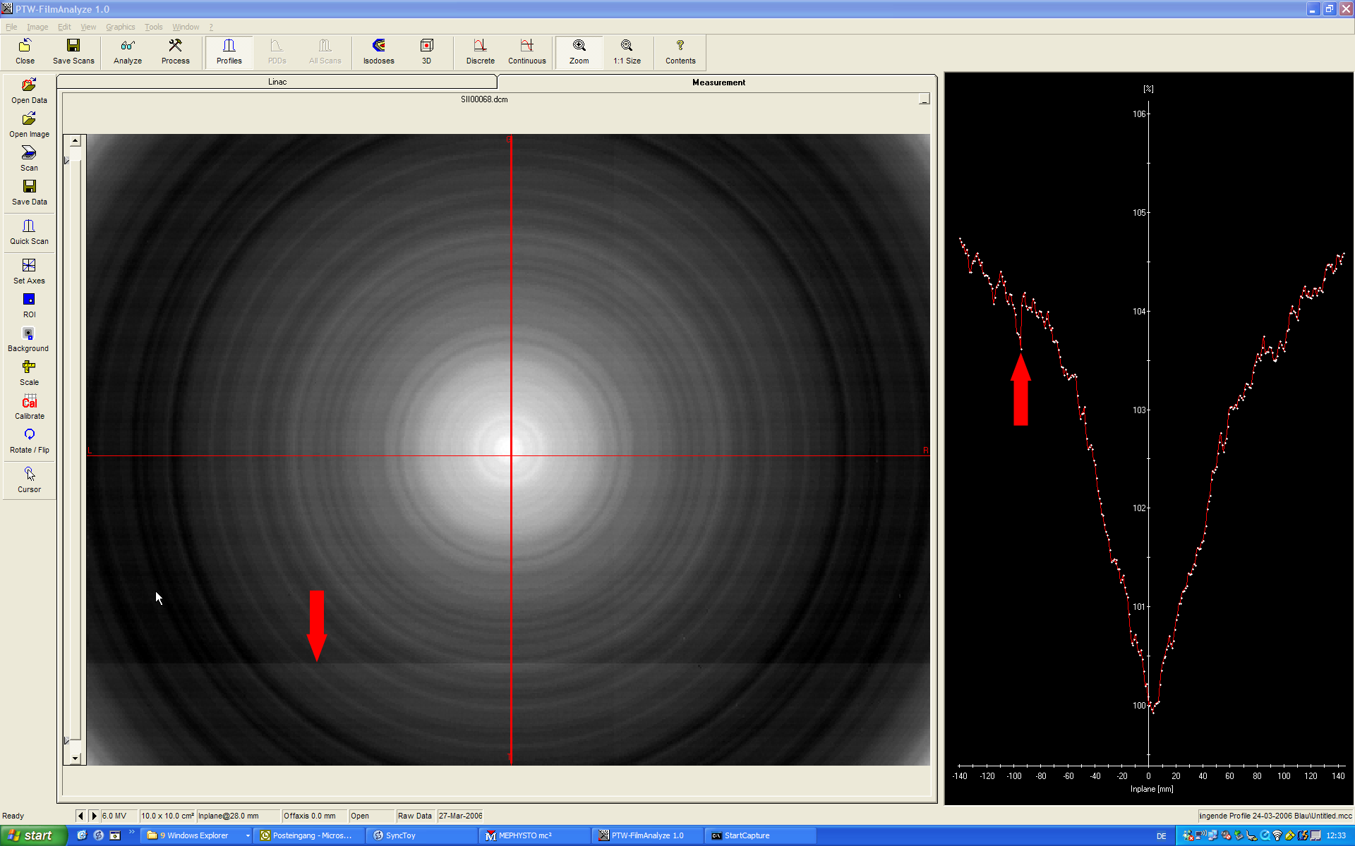
Fig.1: With 300 frames flood-field calibration, a horizontal stripe appeared in the image, the resulting dose step is 0.5% (arrows).
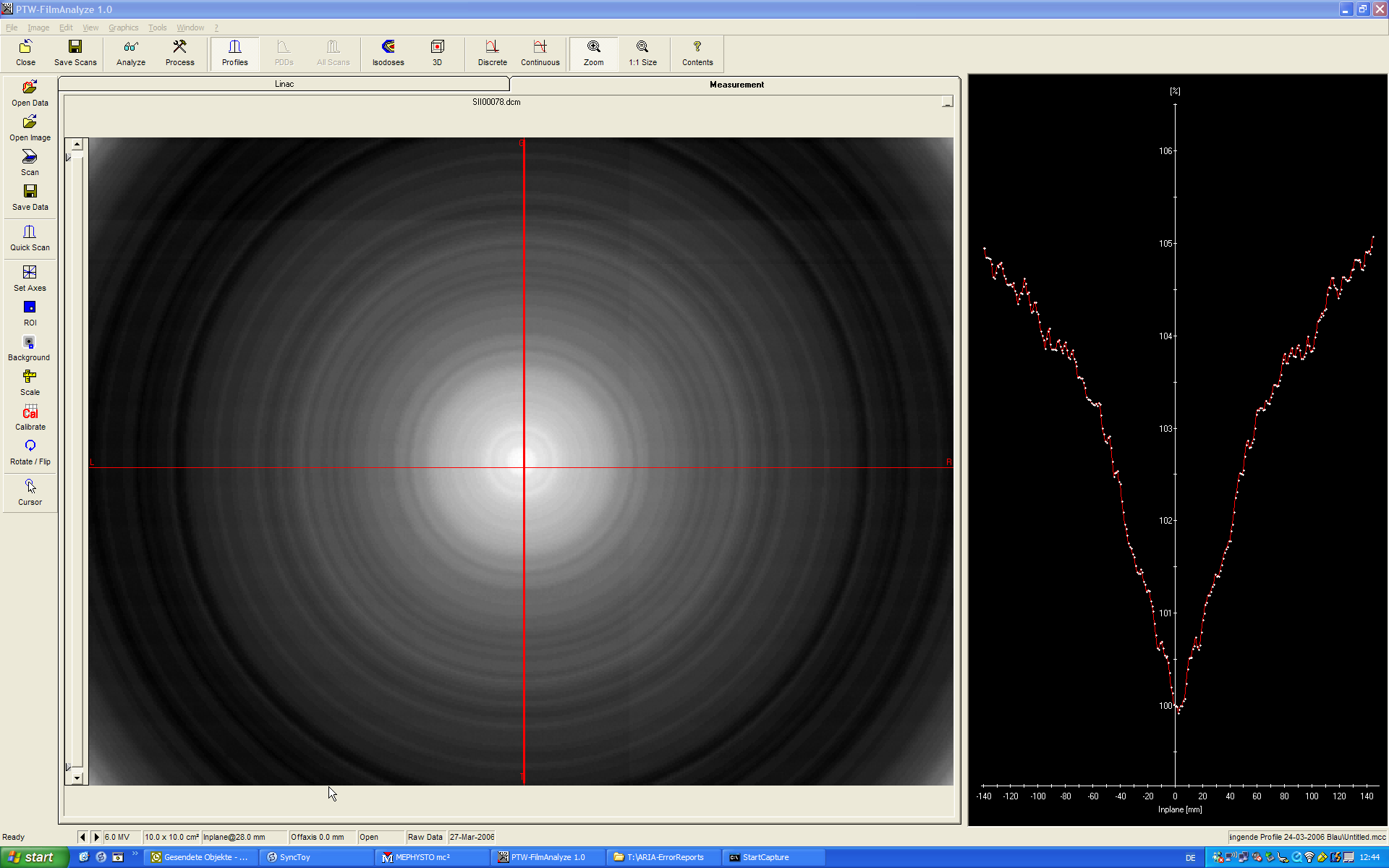
Fig.2: Calibration with 1000 frames, acquisition with 300 frames. No stripes.
The steps are the same as described elsewhere, except for the 105 cm calibration distance. A wizard guides through Dosimetry Calibration in AM-Maintenance (Maintenance > Dosimetry Calibration ...).
If the required diagonal open beam profiles are not at hand, we can provide one for 6 MV and 15 MV. Use at your own risk.
When AM-Maintenance says it waits for the beam, it is highly recommended to wait an additional 10 seconds before beaming on. The yellow beam cone should appear instantly in the wizard's window when the linac starts ticking. We usually beam 200 MU and enter the value 2 * 0.907 CU = 1.814 CU for the corresponding dose. The value 0.907 comes from (100 / 105)^2 (inverse square law). If you beam-on 100 MU (10x10 field) with the effective point of measurement (center pixel) at isocenter, it will give 1 CU. Note: any deviations of the linac output from the reference output have to be compensated!