On Varian linacs, the dynamic wedges (Enhanced Dynamic Wedge - EDW) only work in the gun-target (inplane) direction. Either the Y1-jaw (target-side) or the Y2-jaw (gun-side) closes in after a open beam phase, thereby giving the desired effect.
When DAVID is installed, this means that the wires run parallel to the Y-jaw's edge, which makes DAVID ideal for EDW-QA.
The maximum start position for the jaw that moves is 20 cm (the opposite jaw is always stationary). On the opposite side, the maximum jaw position during EDW is 10 cm, since each Y-jaw has a maximum overcenter travel of 10 cm. This means that the maximum possible EDW field size is (asymmetric) 30 cm. In X-direction, the maximum jaw opening is the full 40 cm.
In the following animation, a measuring sequence for a 30° EDW field is shown. The wedge is oriented in the "In" direction (the naming convention comes from the hard wedges). After an initial open beam phase (which serves for a dose pedestal) the Y1-jaw moves in from the target side (the right side in the animation). Since the field is asymmetric, the bars are not centered.
Of course, it it not possible to derive a wedge angle from such a measurement. The connection would have to be done during machine commissionning. But once the DAVID baseline is established for each wedge angle to be checked, the EDW-QA is straightforward.
Here is a 60° wedge, same field size and orientation:
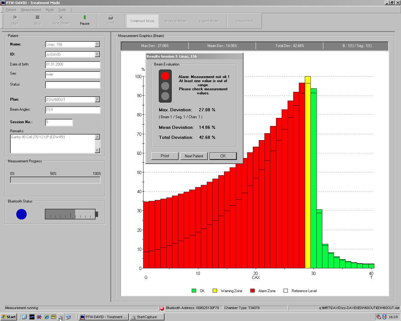
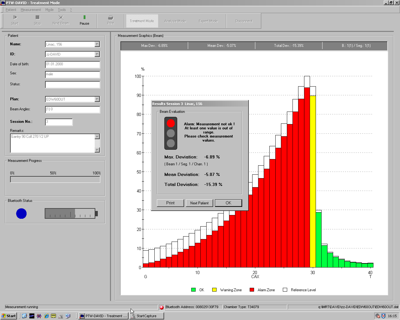
The following animation shows that not all bars are green all the time. Maybe due to the Y1-jaw moving down (which is the case when Gantry is 90°, collimator is 270° and wedge direction is IN), there is a warning-level deviation for channel 11:
Here are two more examples:
- If a 45° wedge is delivered instead of the intendend 60° wedge, the resulting dose deviation can't be overlooked.
- In service mode, with some overridden interlocks, an EDW treatment could be provoked which didn't start with the typical dose pedestal (open field), but which started with the jaw sweep phase right from the beginning. This is the result.