

Due to its small leaf width and its low transmission, the HD120 High Definition MLC of the TrueBeam STx is ideal for shaping small and medium size fields. But in large fields (static, IMRT or RapidArc), it can be the source of undesired dose outside the intended treatment field, by means of scatter from the MLC leaves. Here, we will simply call this "out-of-field dose".
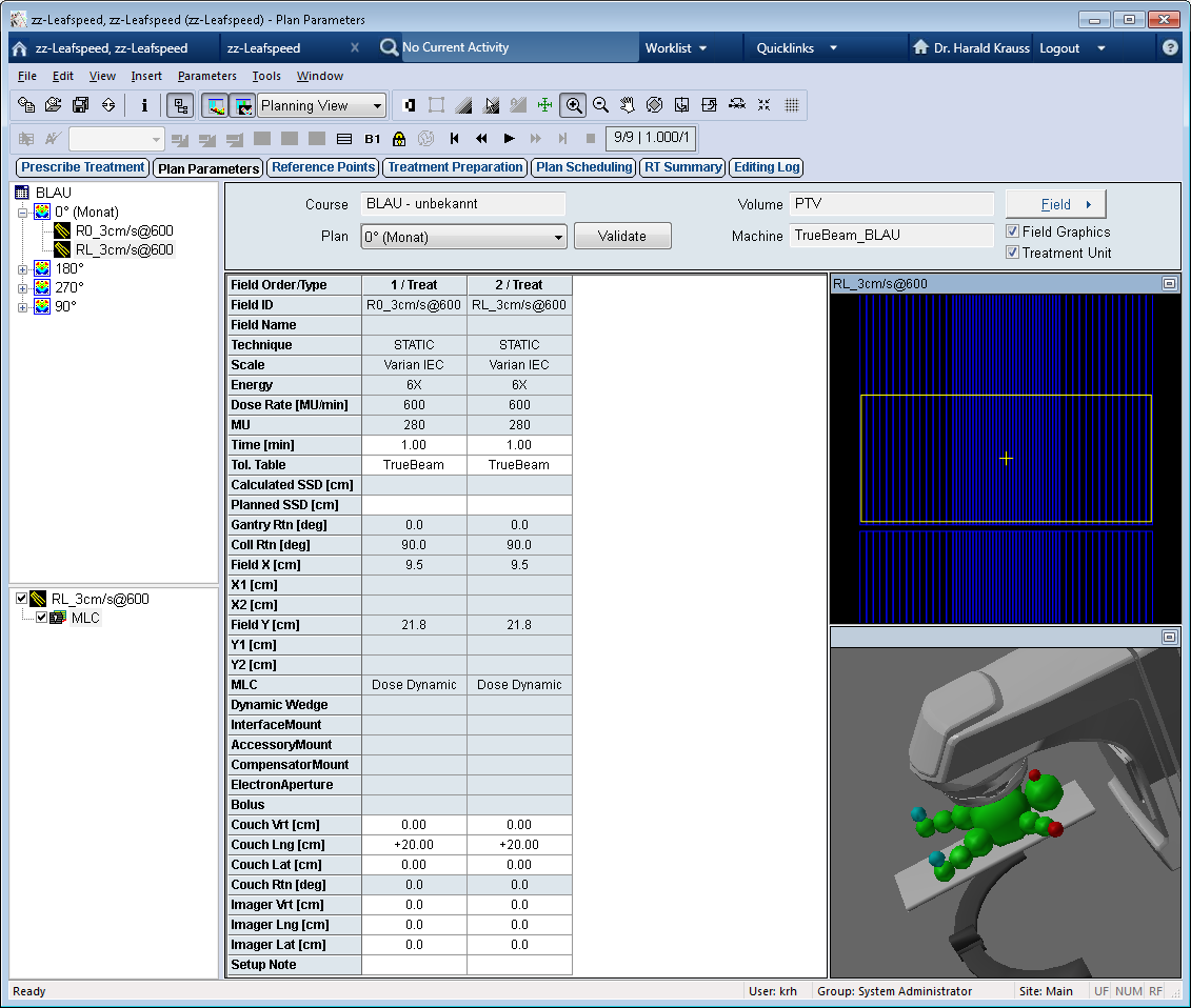
During acquisition of the following dosimetry image, a 5 mm wide sliding window moved in the vertical direction (90° collimator rotation). The out-of-field dose is located in the areas under the Y jaws, and is clearly visible on the 2D distribution and the dose profile:
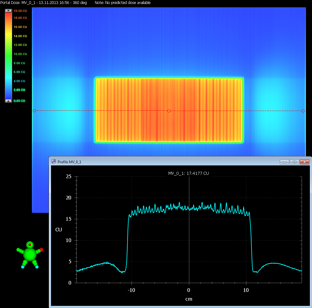
When the top edge of a certain leaf pair is hit by the beam, radiation is scattered in all directions. In a simplified picture, the scatter from leaf pair N is blocked by neighbouring leaf pairs N-1 and N+1, which works except for the first and last leaf pairs.
Shielding by Y jaws in such a case does not work, because jaws are closer to focus than the MLC. In the above example, the Y jaw setting was 21.8 cm, which means that there was only a 1 mm overlap between leaf and Y-jaw on each side.
In principle, due to Varian's tertiary MLC design, all Varian MLCs scatter under the Y jaws. But in contrast to the Millenium-120 MLC (which covers a field size of 40x40 cm), the HD120 shows this effect already at moderate off-axis distances.
Clinical Example
The phenomenon is not restricted to test patterns. It can be seen in many clinical MLC fields. But before Eclipse 13, it was only visible in measured dose distributions. In Eclipse 11 and earlier versions, this scatter component was not modeled, and was therefore not included in the calculated dose distributions.
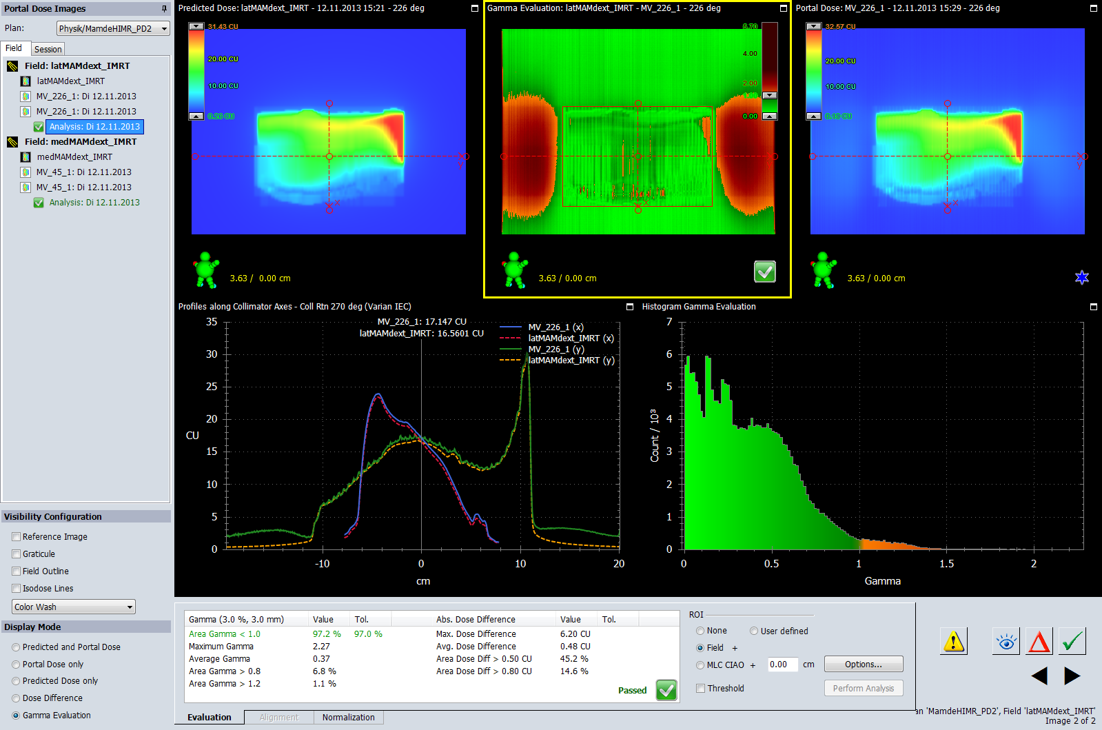
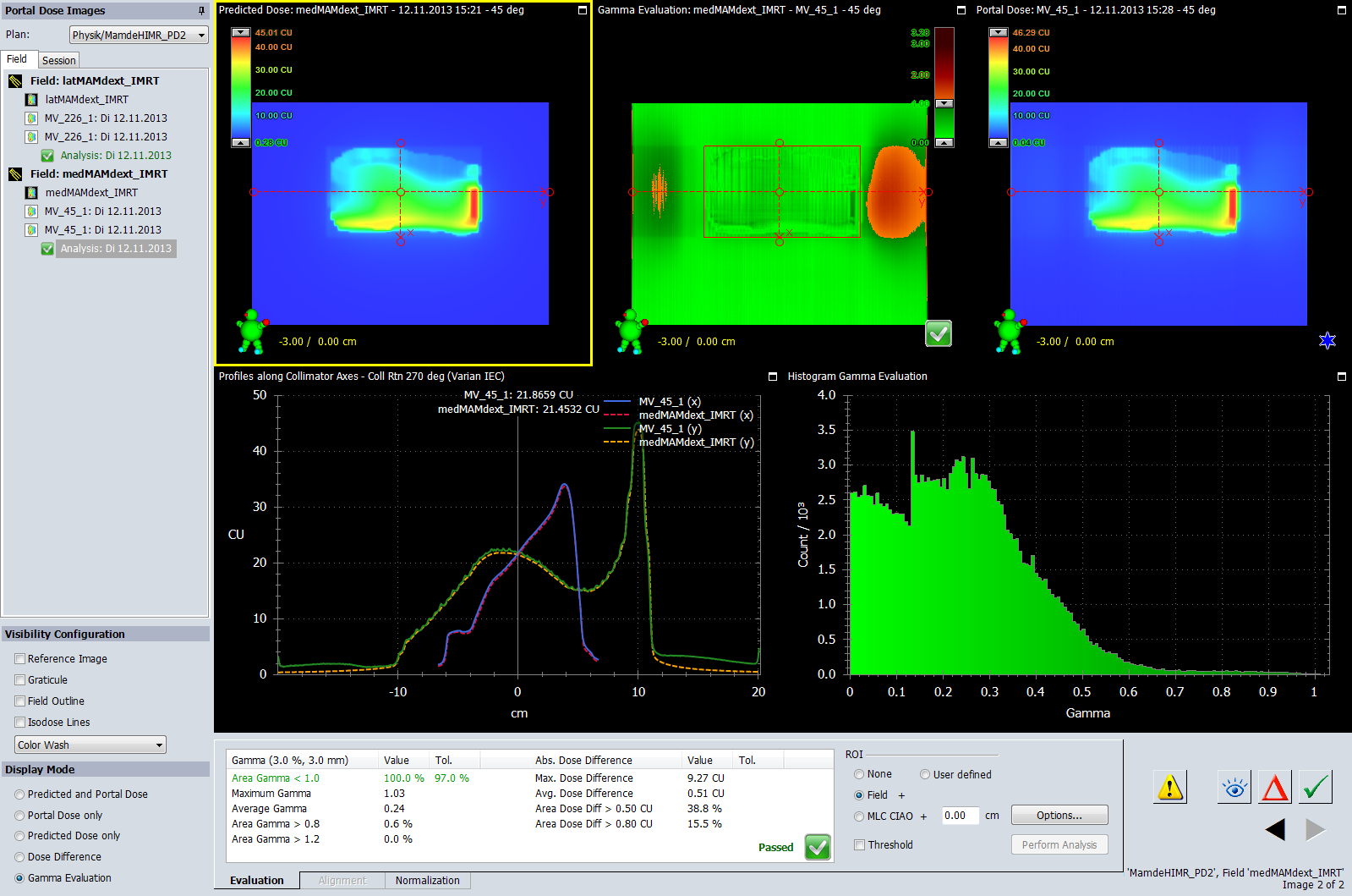
The following example shows two large IMRT fields (sliding window technique) with multiple carriage groups, taken from a Hybrid-IMRT breast plan. The MLC (blue) is displayed on top of the fluence distribution (grey). According to our theory, the fields should show different levels of out-of-field scatter:
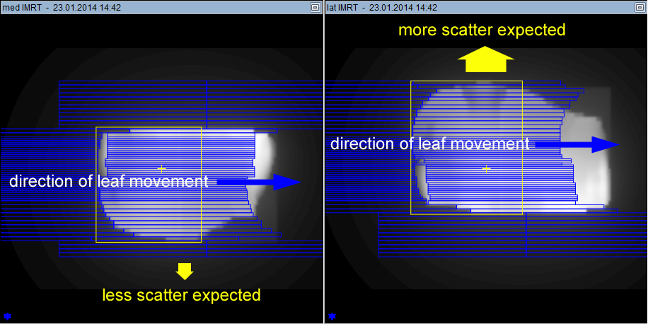
In the left field (medial field), the Y1 jaw (bottom edge of yellow rectangle) is set to 9.2 cm. This means that there are three additional leaf pairs which are not irradiated and therefore provide additional shielding. Out-of-field scatter should be moderate.
On the right field (lateral field), the Y2 jaw is set to 11.0 cm (top edge of yellow rectangle). The outmost leaf pair takes part in the sliding window sequence which shapes the beam. Since there is no leaf pair next to it in Y2 direction which could block outwards directed scatter, more out-of-field dose is expected for this field.
Fortunately, in both fields the scatter direction is in air, due to the tangential field arrangement on the patient (the fluence distributions reflect the shape of the breast).
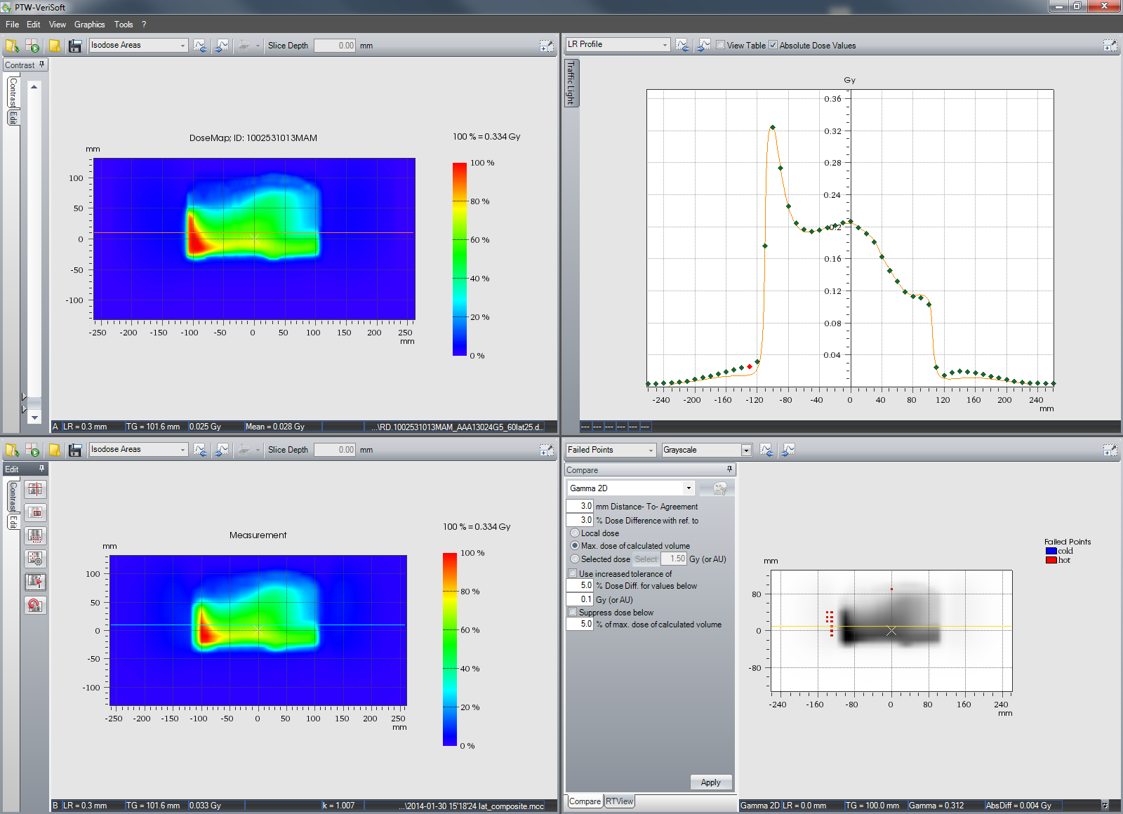
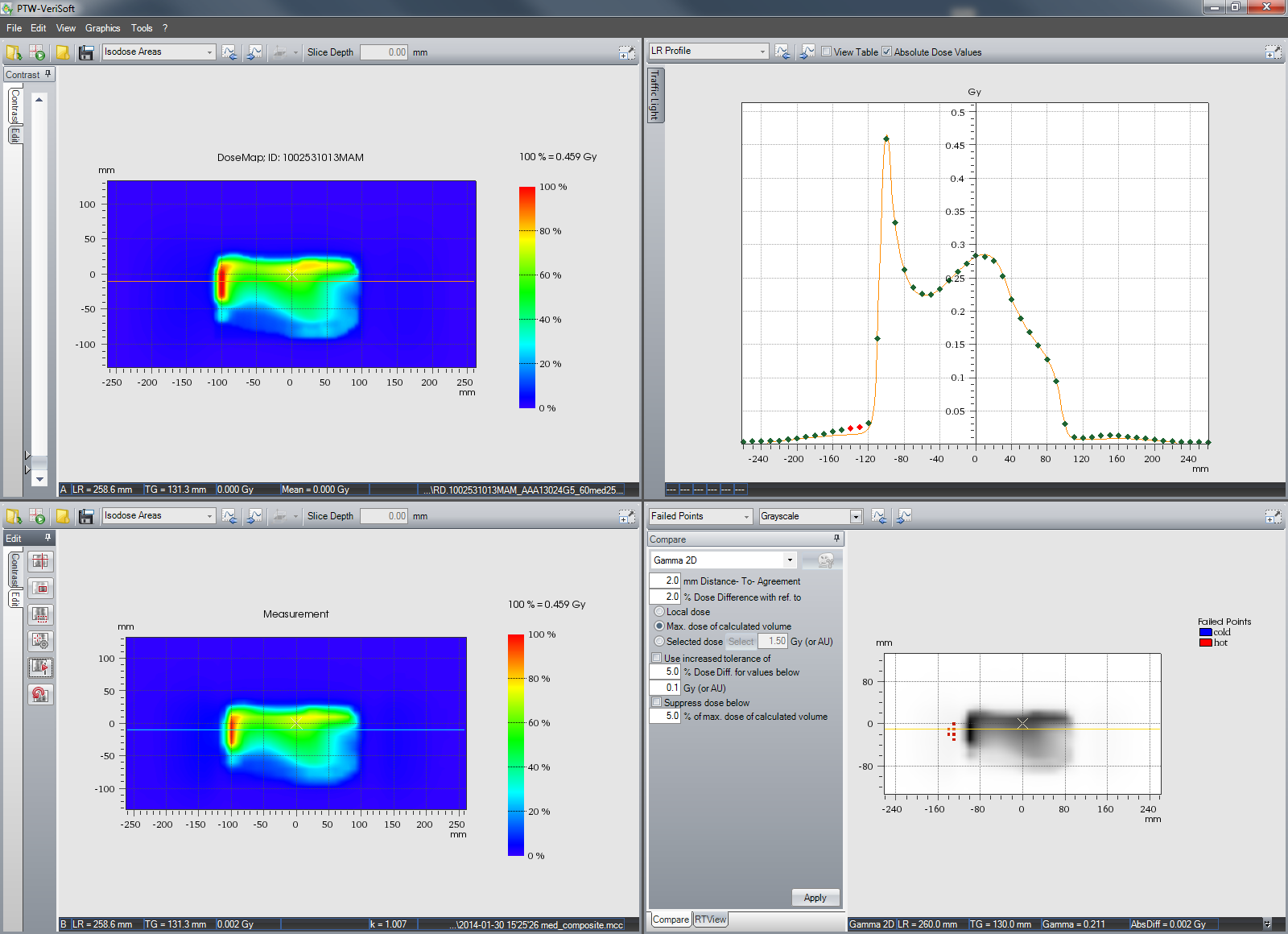
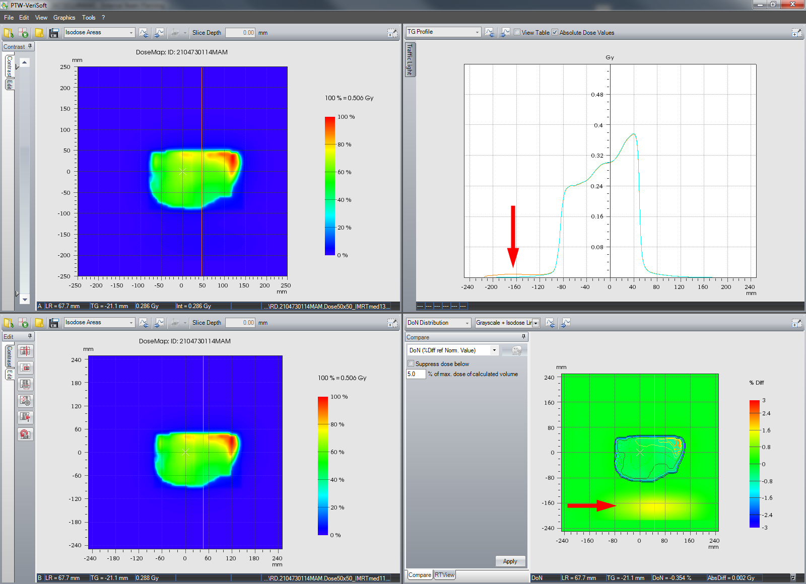
The following two VeriSoft images compare for the medial and lateral fields the dose distributions in phantom (depth 3.9 cm polystyrene) calculated with AAA 13.0.24 (top left) and AAA 11.0.31 (bottom left). The dose area displayed is 50 x 50 cm.
The red arrows point to the area of out-of-field dose, which shows up in the inplane dose profile of the AAA13 calculation (orange), and in the dose difference between AAA13 and AAA11 (which does not model of out-of-field scatter). For the medial field, dose difference between the two calculations is about 1.5% of field dose max:
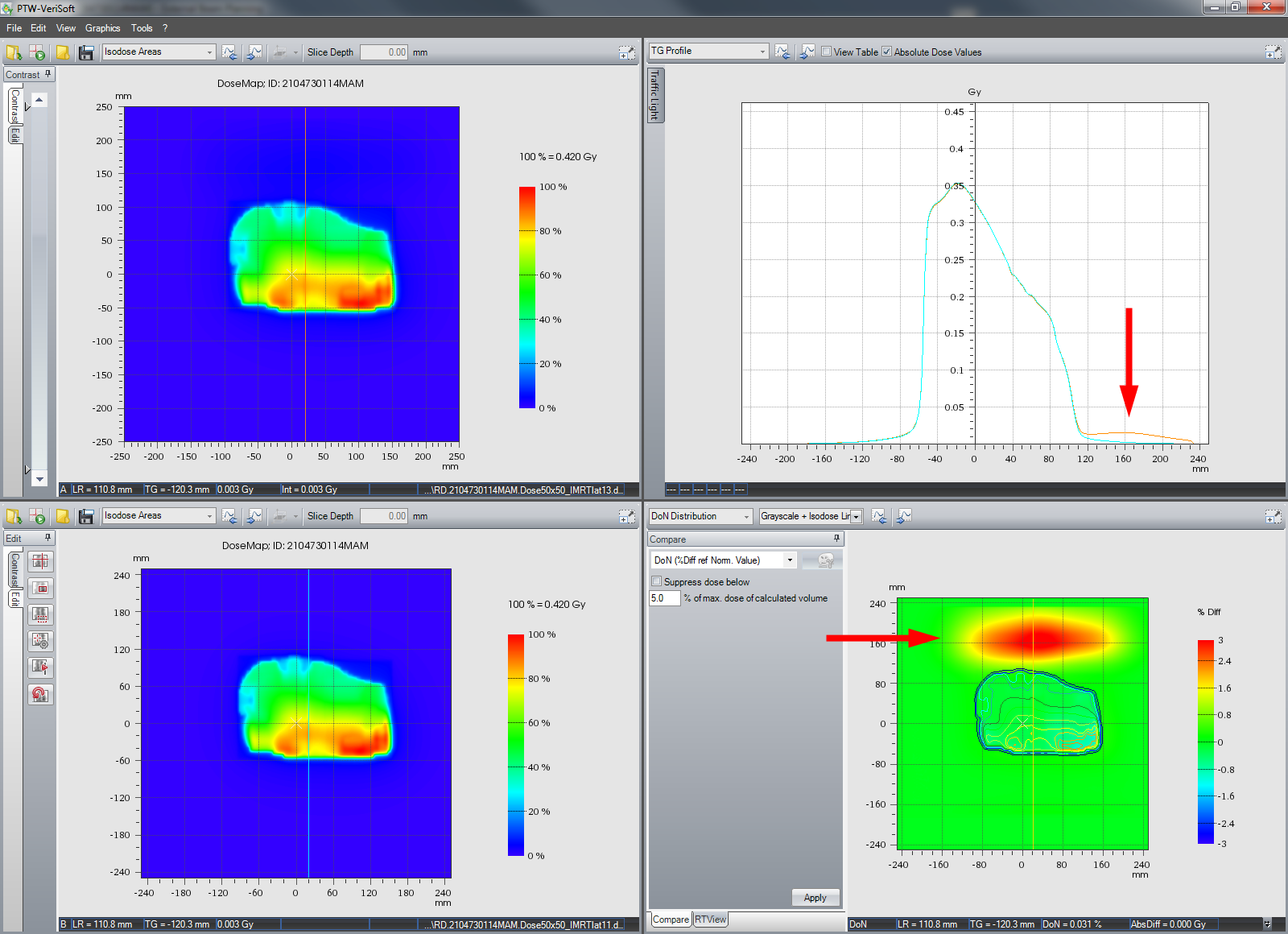
For the lateral field, scatter is much larger (as expected). The difference between AAA13 and AAA11 is up to 3.2% of field dose max:
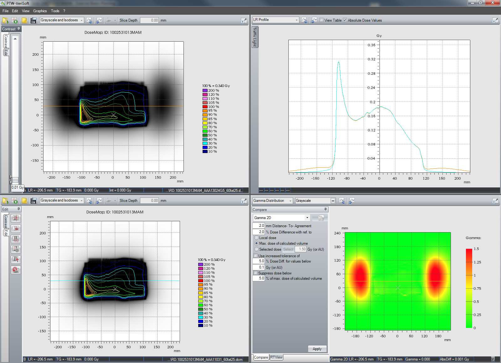
The next image compares AAA13 (top left) and AAA11 (bottom left) calculations for another breast field. Collimator is at 90°, leaves move in the vertical direction. The zone under the Y-jaws is therefore left and right. Window/levelling was set to lowest possible dose range (0.00 - 0.01 Gy). This way, the calculated out-of field dose becomes directly visible:
Conclusion
Large fields need to be treated too, and if no other linac model is available, they need to be treated on the TrueBeam STx.
When pushing the field size limits of the HD120 MLC, the user encounters out-of-field dose caused by scatter from the outmost leaf pairs. Sometimes shifting the isocenter a little helps a lot (if there is room for shifting, which means that field length is still less than 22 cm). For VMAT, at least jaw tracking should be active, which helps keeping the jaw opening to a minimum at all times. For large breast fields, it should be checked whether out-of-field dose is an issue at all (or whether radiation scatters outside the patient and does no harm, see example above).
Physics on the linac of course has not changed with Eclipse13, and the actual dose distribution in the patient is still the same. But at least now the MLC scatter contribution to out-of-field dose is modeled in Eclipse and is therefore visible in calculated dose distributions and in dose volume histograms.
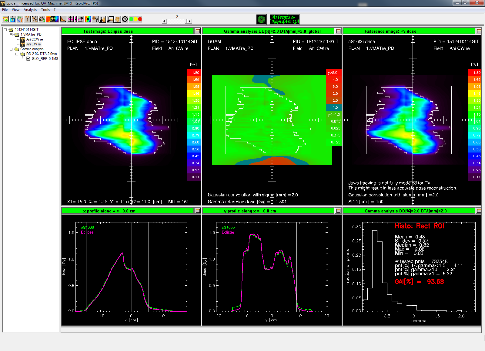
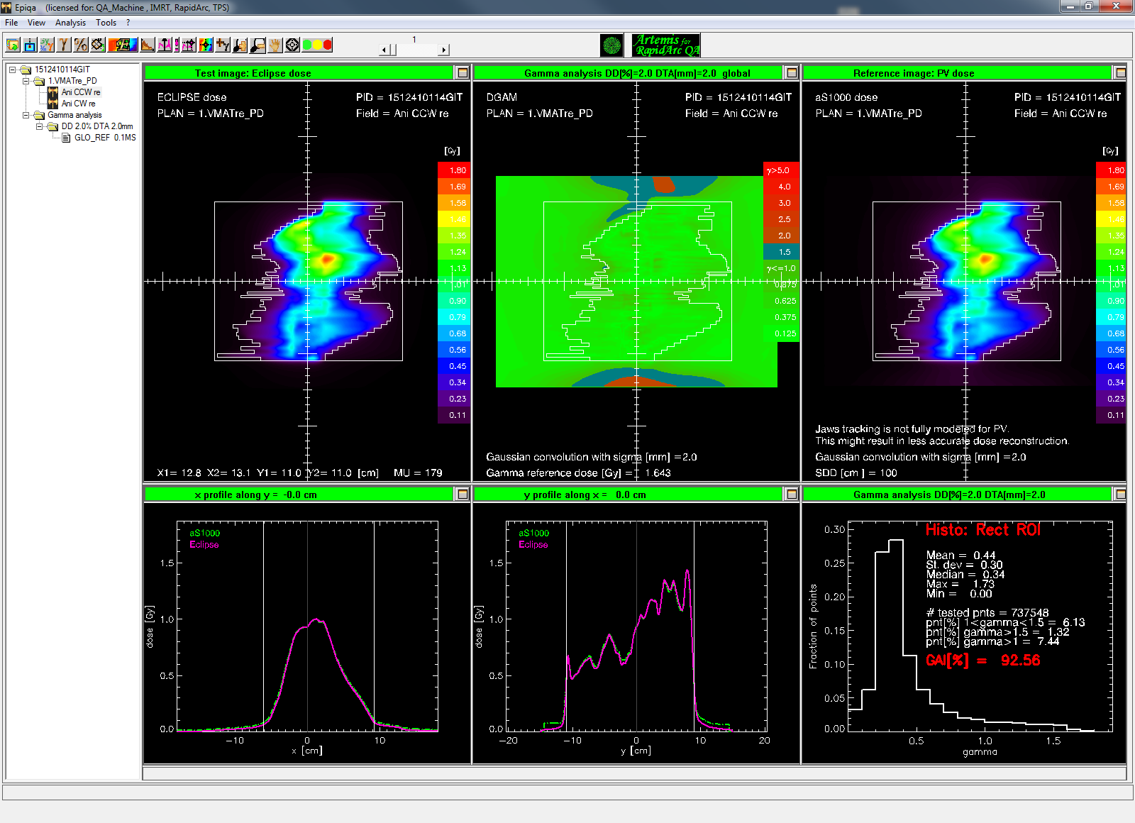
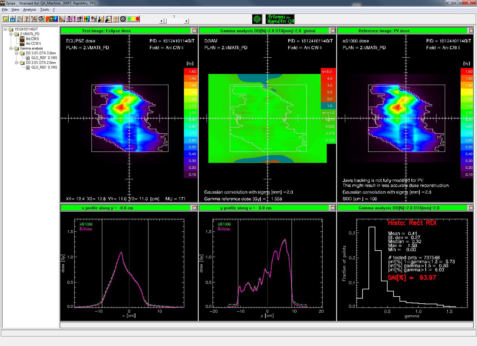
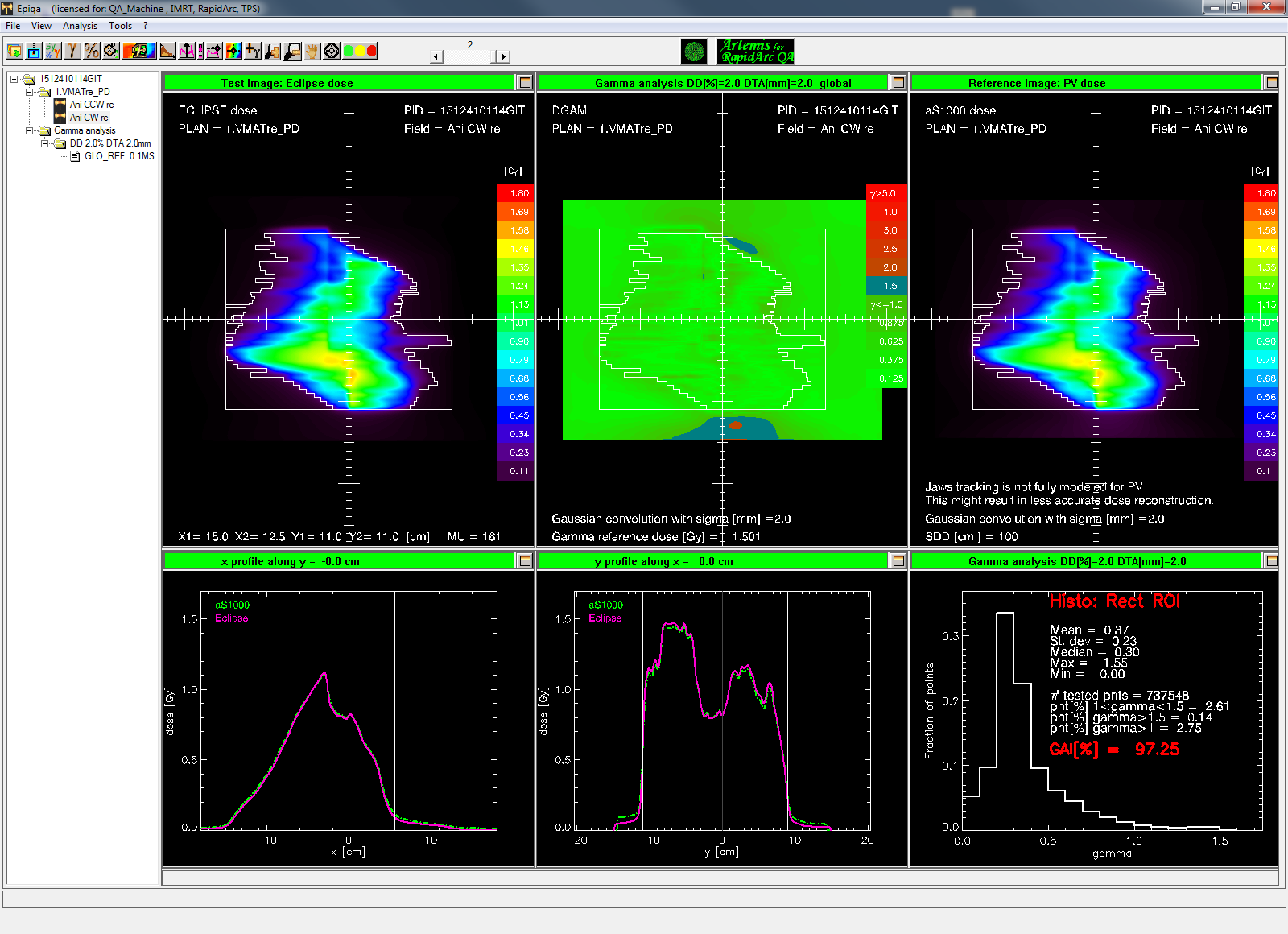
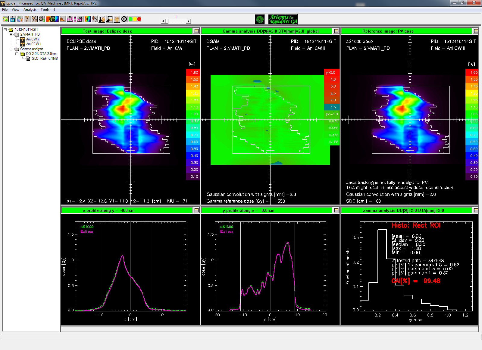
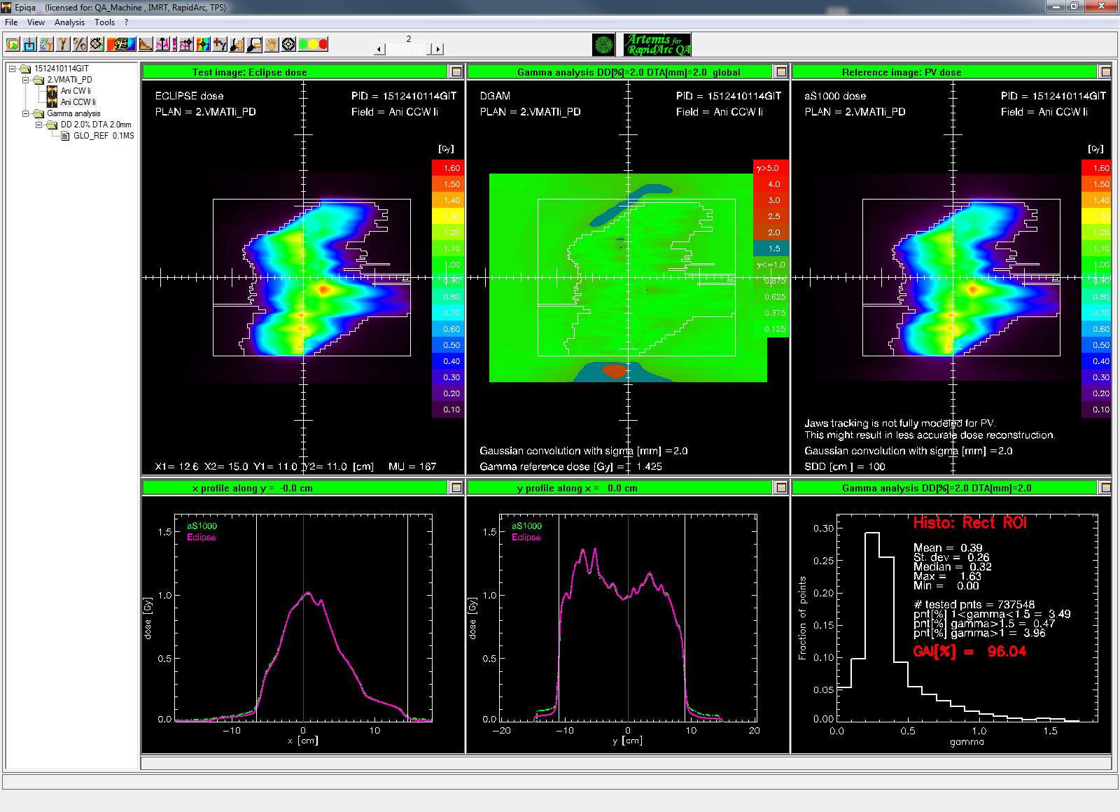
In the first few verification measurements with AAA13, there was still some residual disagreement (see sidebar). However, the modelling of out-of-field dose introduced in Eclipse13 improves the overall agreement during plan QA.