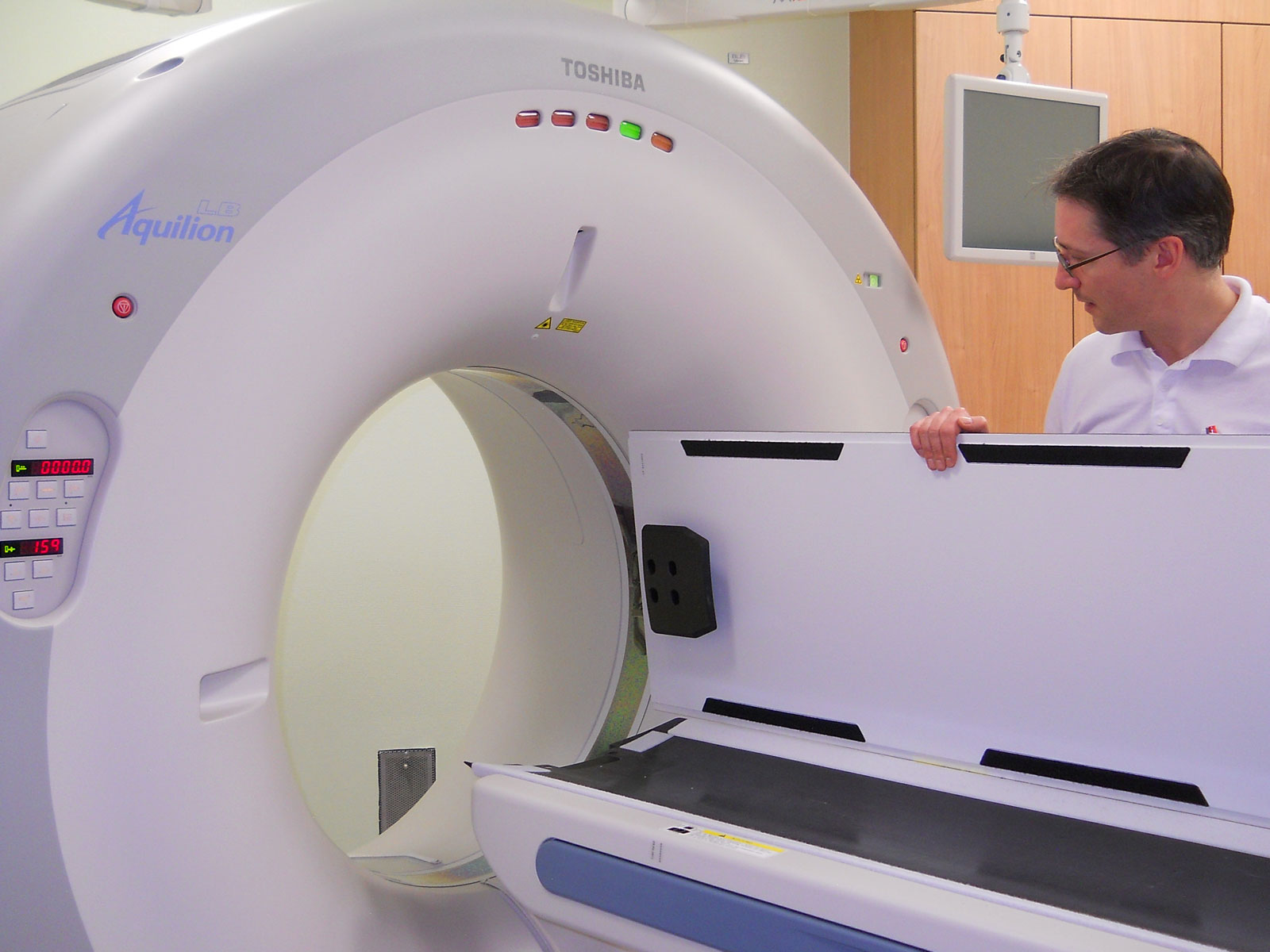
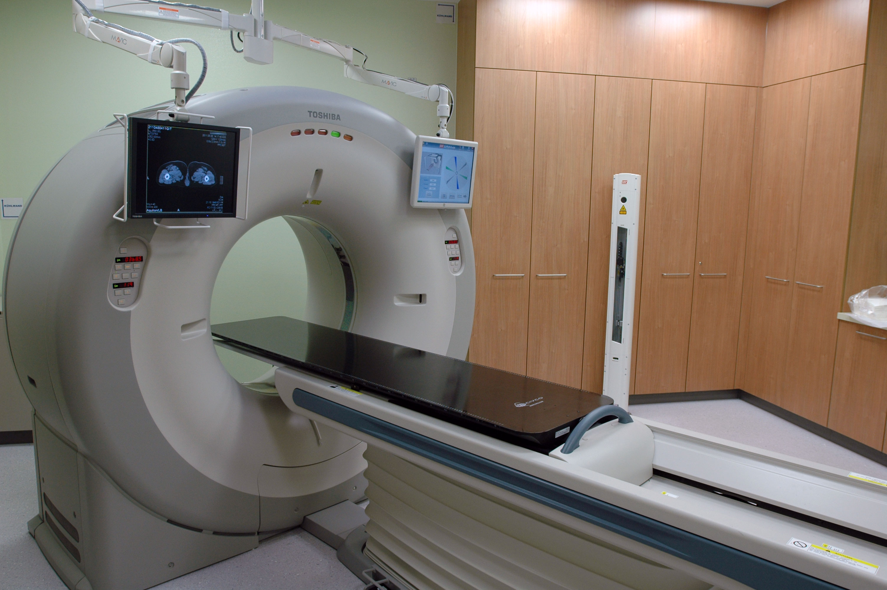
If a CT scanner is not only used for diagnostic purposes but also for CT-simulation (virtual simulation), the performance characteristics of the couch become important.
When the tabletop moves into the Gantry bore during the scan, it is reasonable to assume that the gravitational forces resulting from the patient's mass will bend the couchtop down (compared to the situation without load). Since the couchtop is only supported by the couch base at fixed locations, this could be a problem with heavy patients and large couch excursions.
The anatomic model of the patient which is constructed from the stack of transversal CT images by the Treatment Planning System (TPS) must be spatially accurate in all three dimensions. No image rotation, warping, shearing etc. is allowed. This can only be guaranteed if the scanner's couch fulfills certain quality standards. It goes without saying that the images themselves must have high quality and HU fidelity.
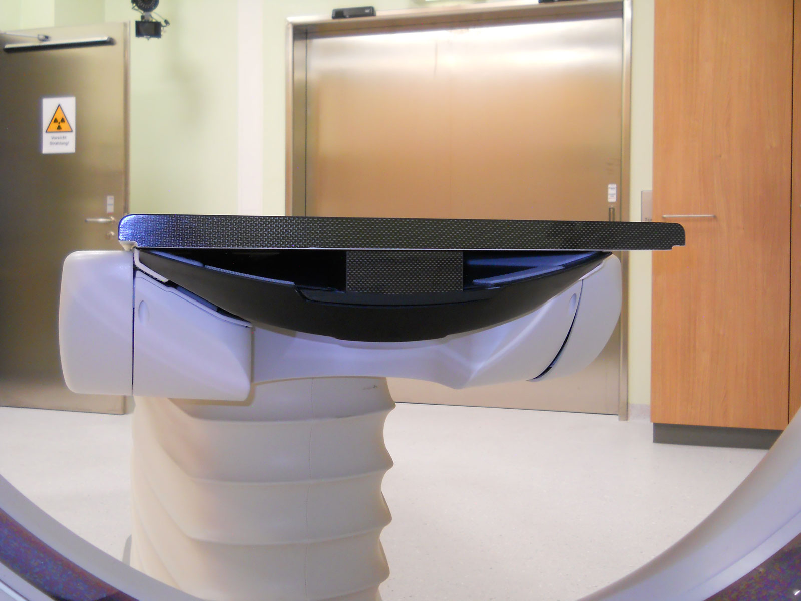
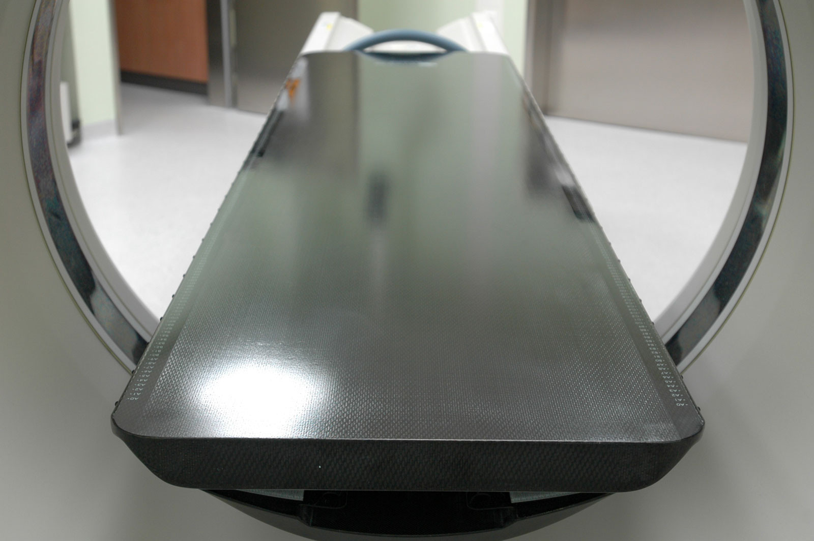
On a CT-Simulator, a flat carbon "overlay" is usually added to the scanner's moving couchtop ("cradle"), which has some similarities with a cantilever. Although the overlay typically snaps into holders and is therefore anchored more or less, it does not automatically increase the second moment of area (which describes the resistance of beams against deflection). This depends in a complicated way on the design, e.g. the location of rolling bearings which act as fulcrums, the position of anchor points etc.
Materials and Methods
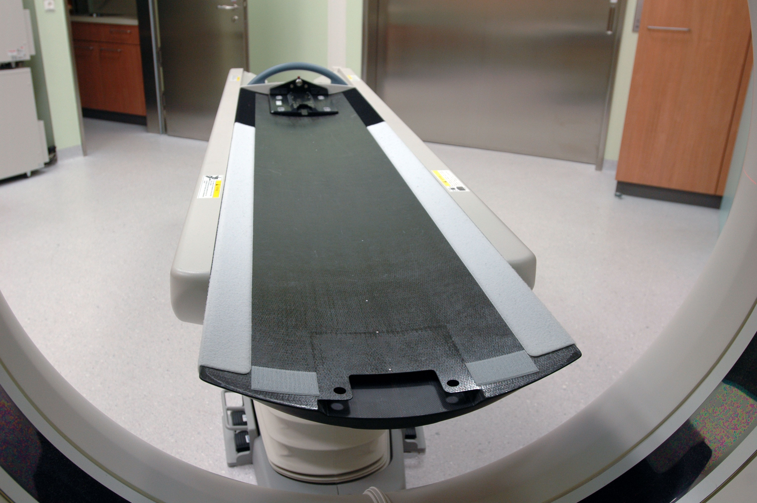
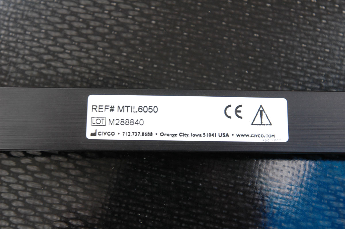
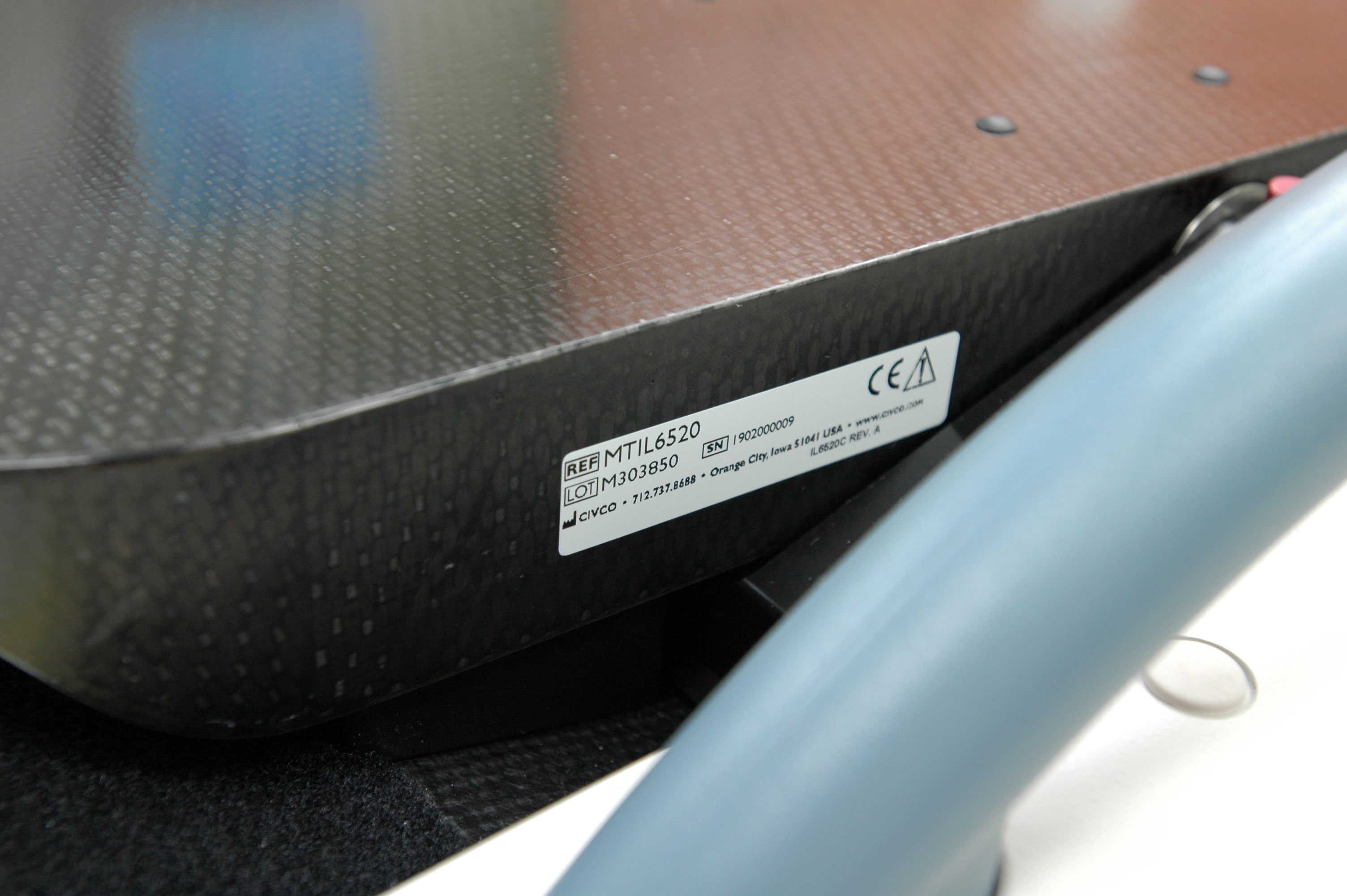
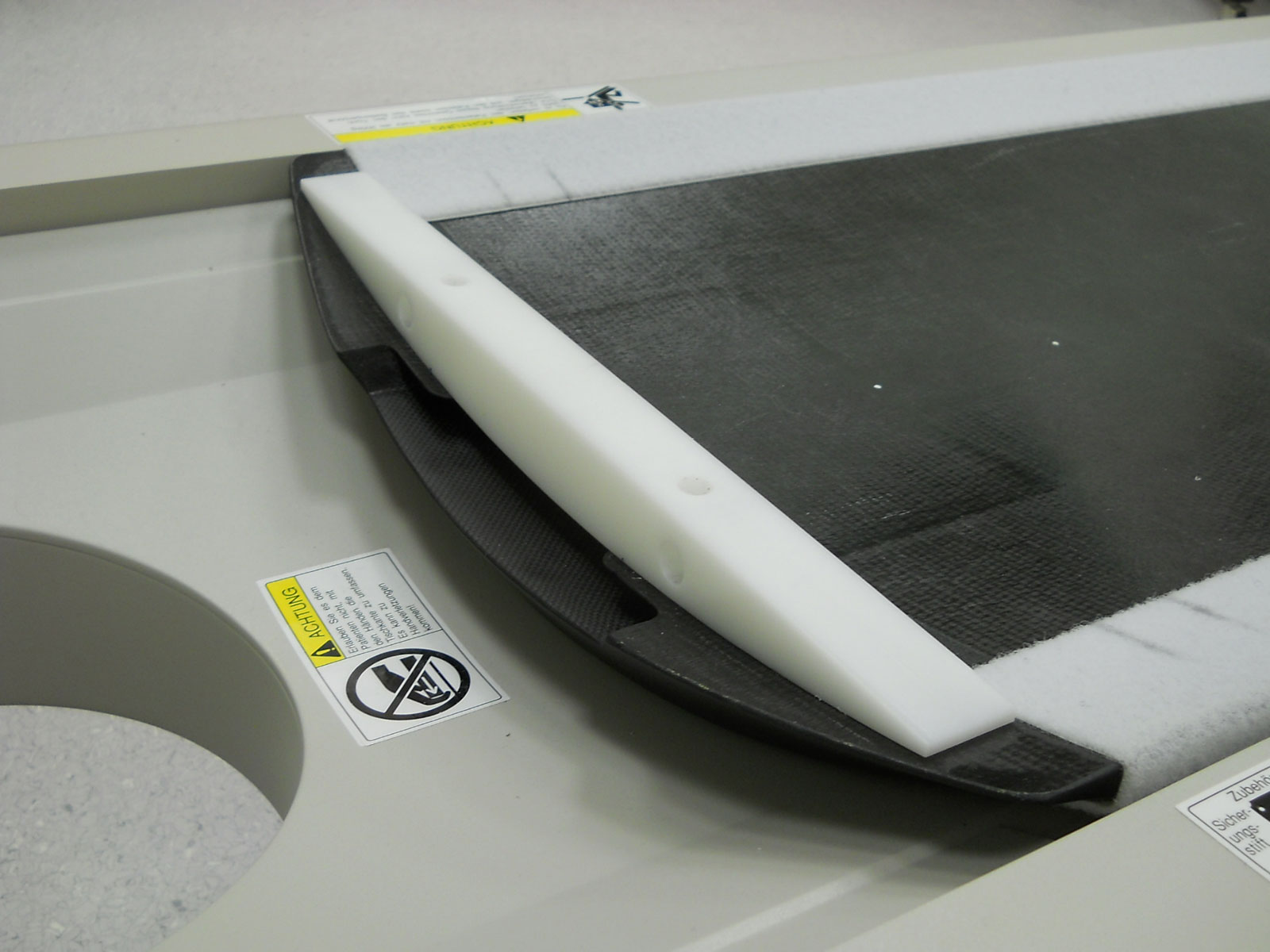
Our Toshiba scanner is currently equipped with a Civco Universal Couchtop™ - One Piece (MTIL6520) overlay, which has an overall length of 216.5 cm, a width of 53 cm, and a thickness of 5 cm (pic1, pic2).
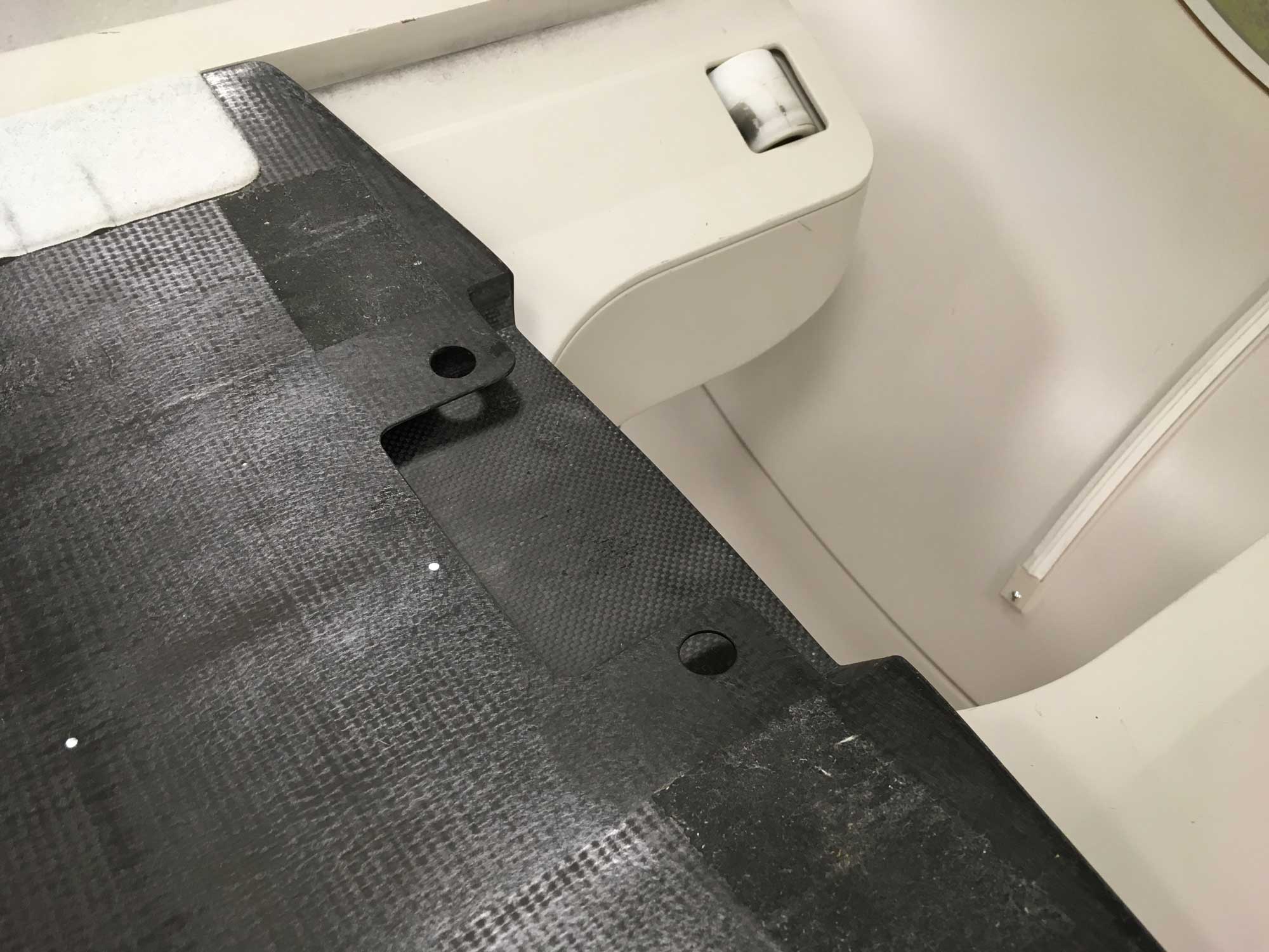
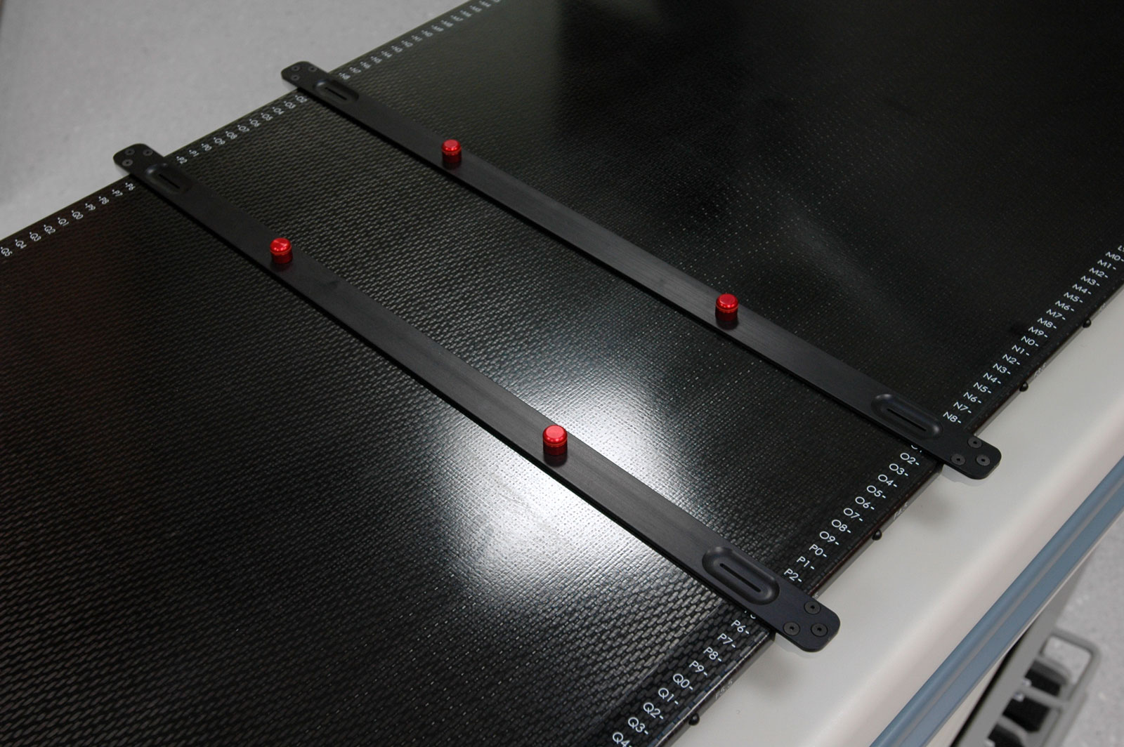
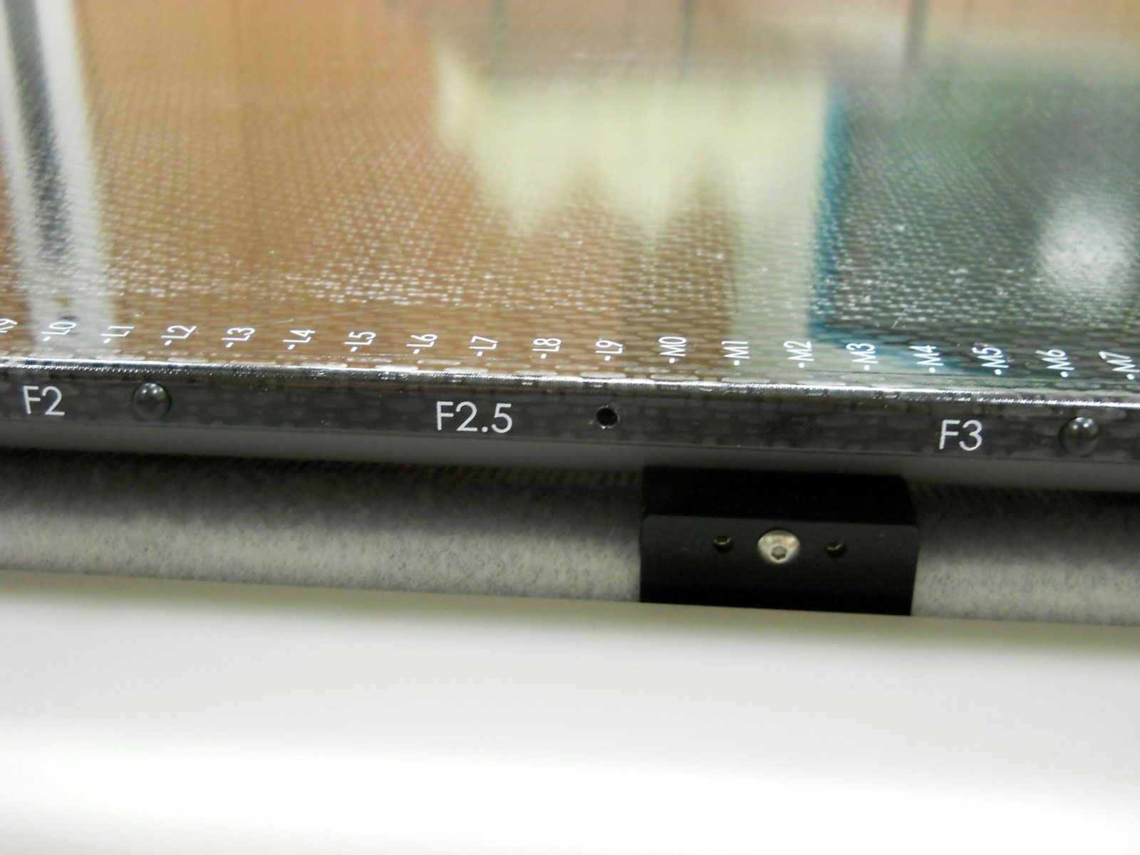
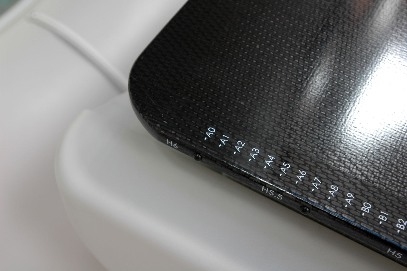
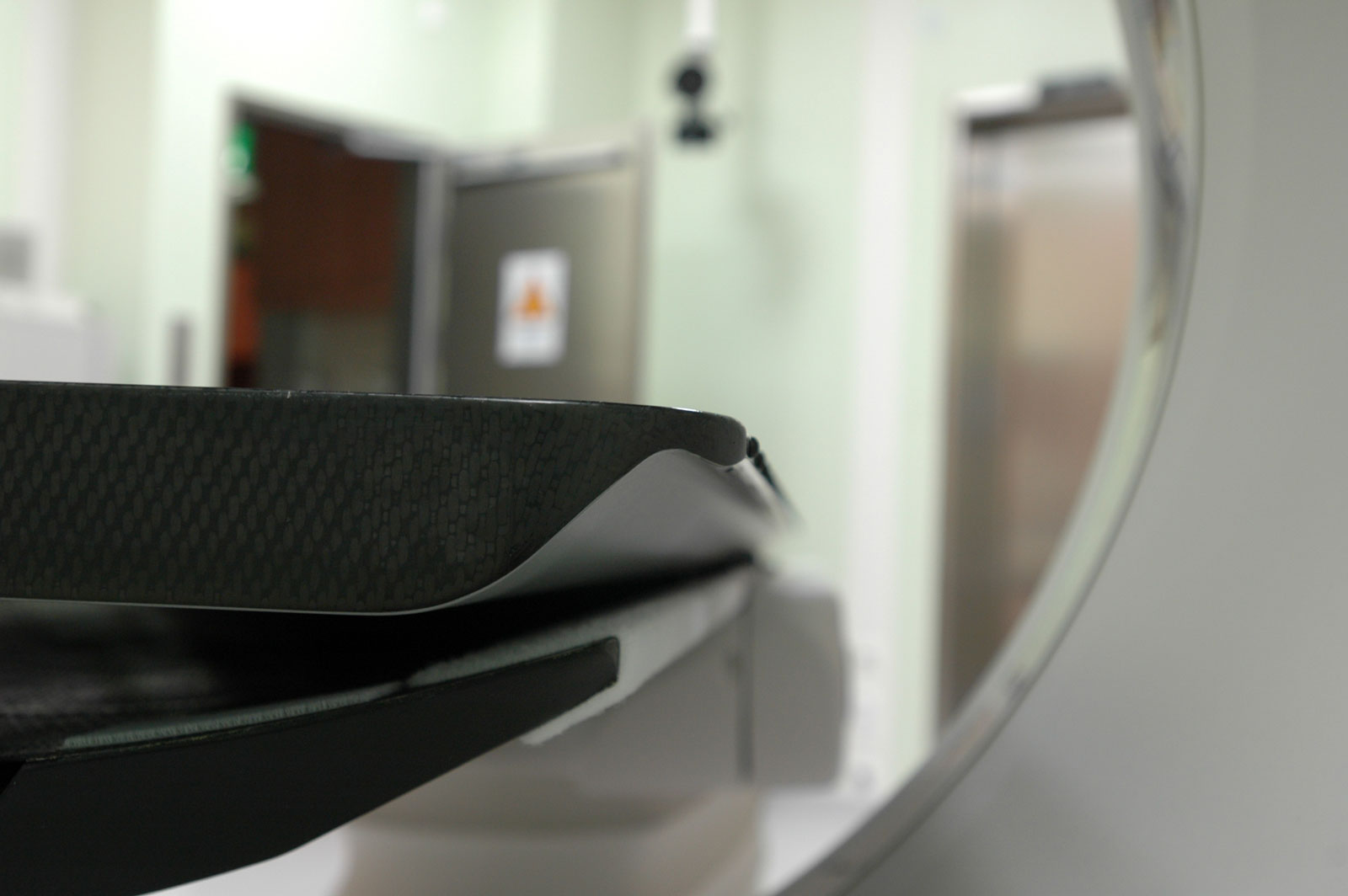
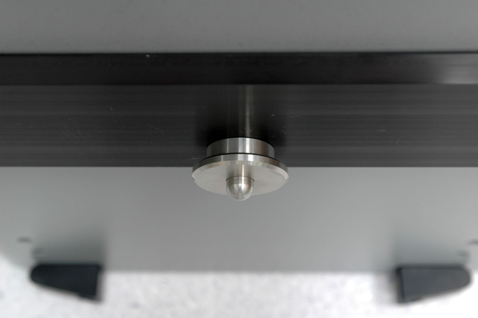
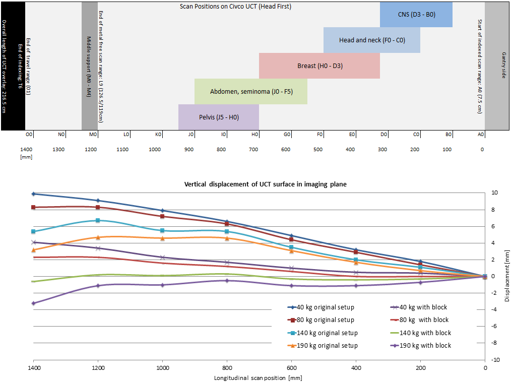
In the original setup, the UCT is supported mechanically on three points: a curved bar which fills the curvature of the cradle is located 126.9 cm from the cranial end (assuming head-first position). The other support points are two small blocks near the caudal end (red arrows):
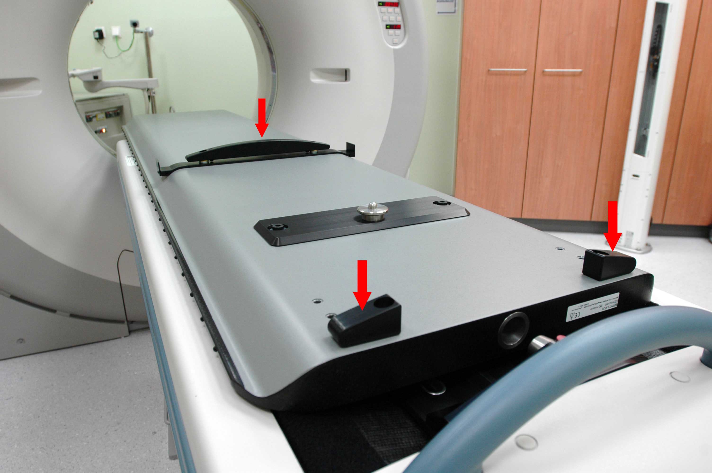
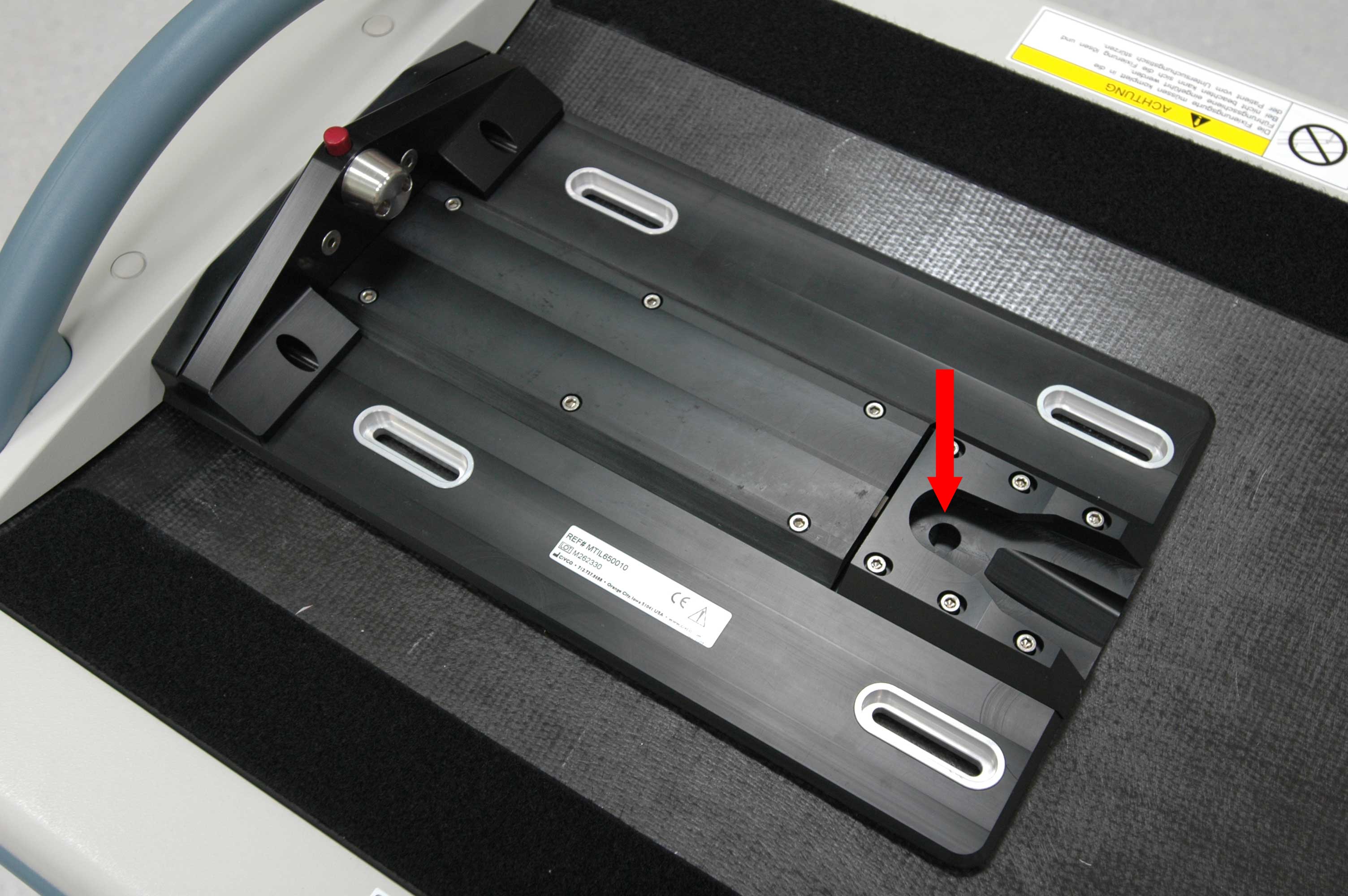
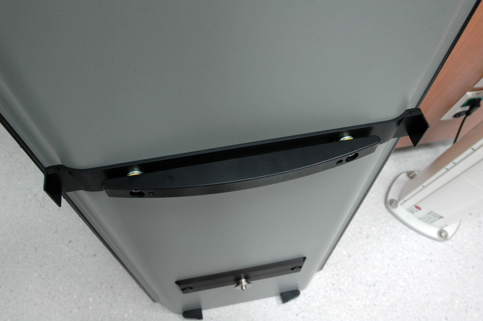
Located between these parts is the "king pin", which snaps into a corresponding base plate. On the Gantry side, the UCT resembles a diving board: it floats above the cradle (red arrows):
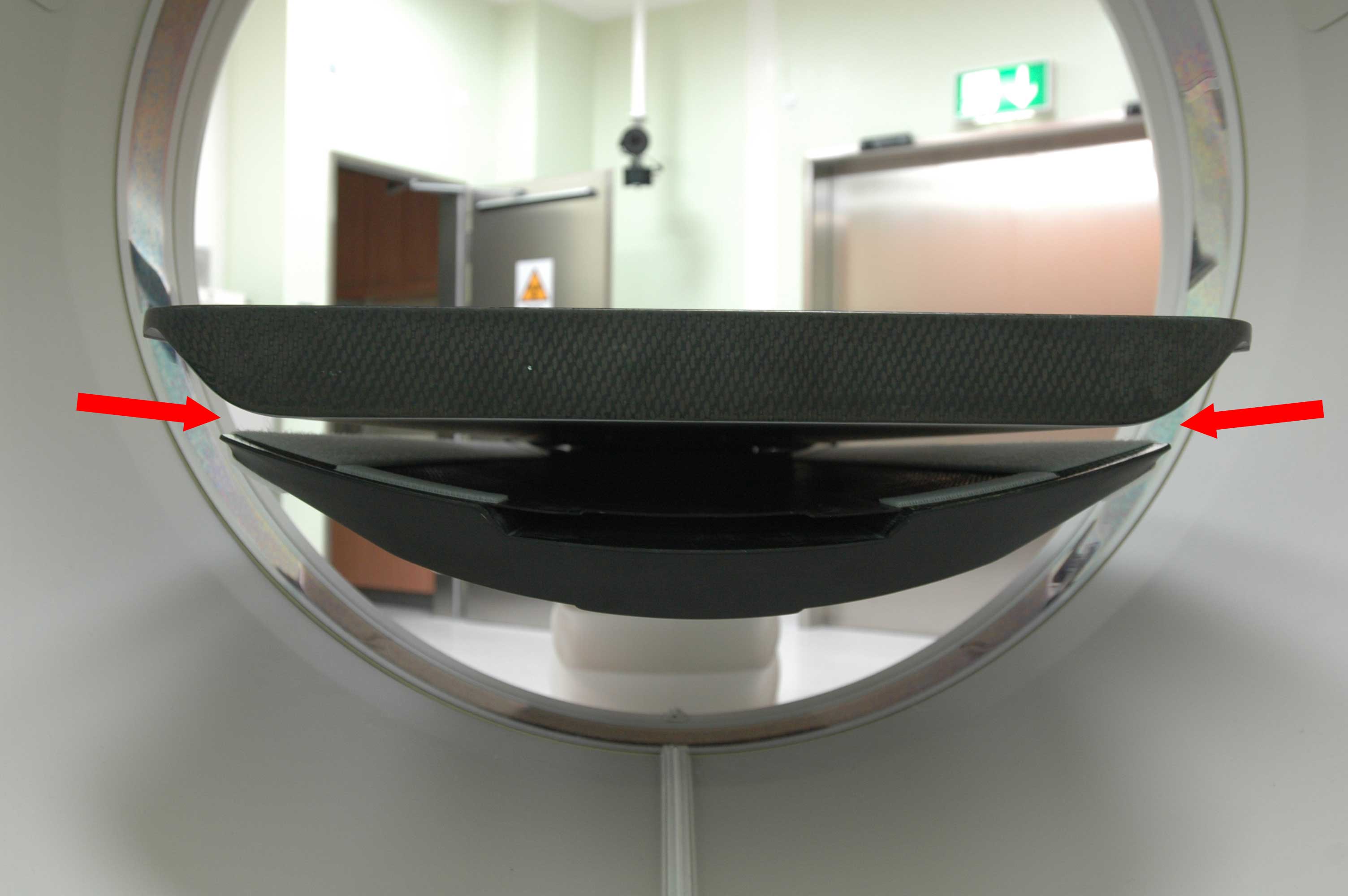
This is in contrast to all other overlays we know, which are usually supported at its two ends (like the CT-403 described in the sidebar).
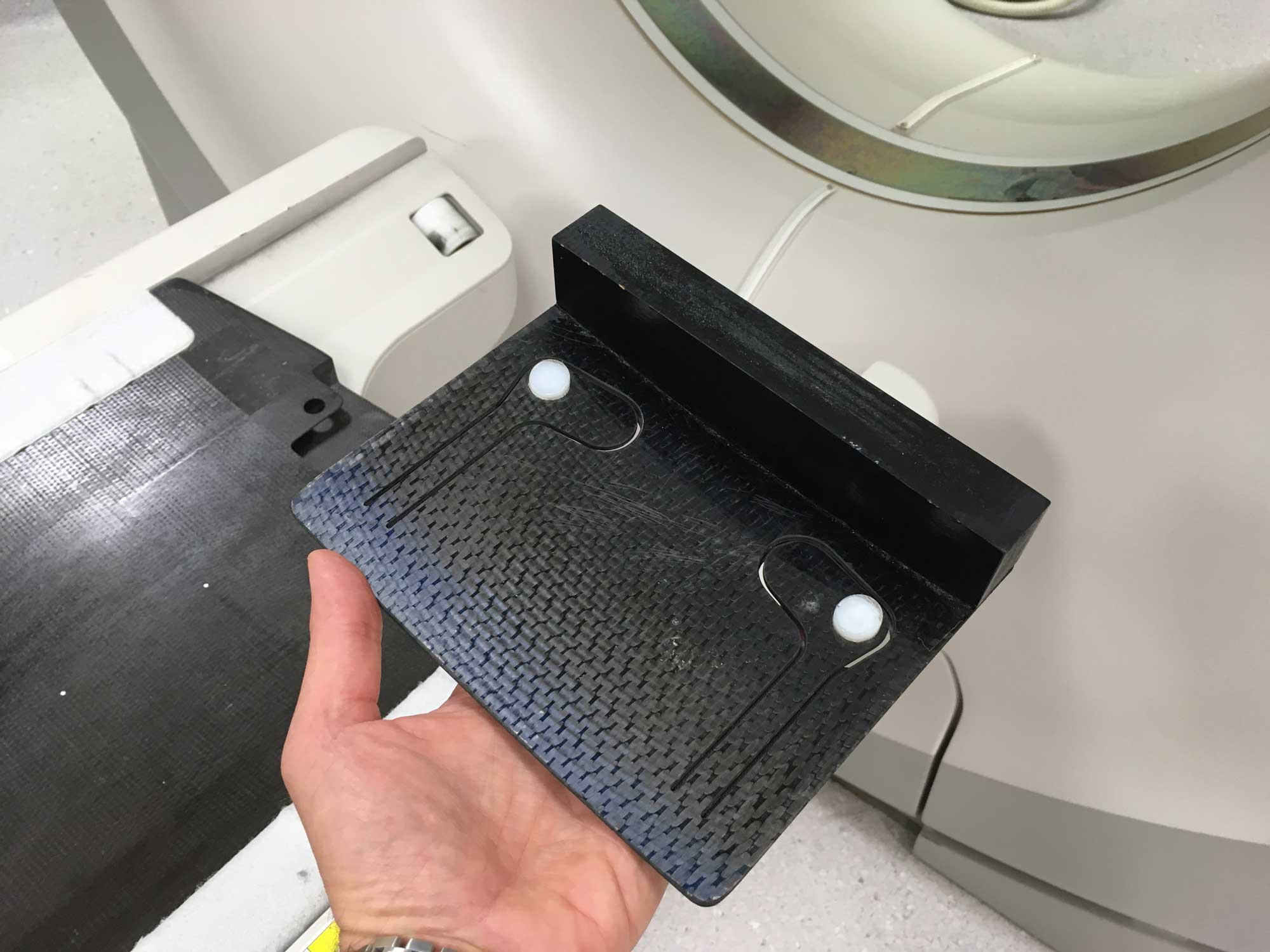
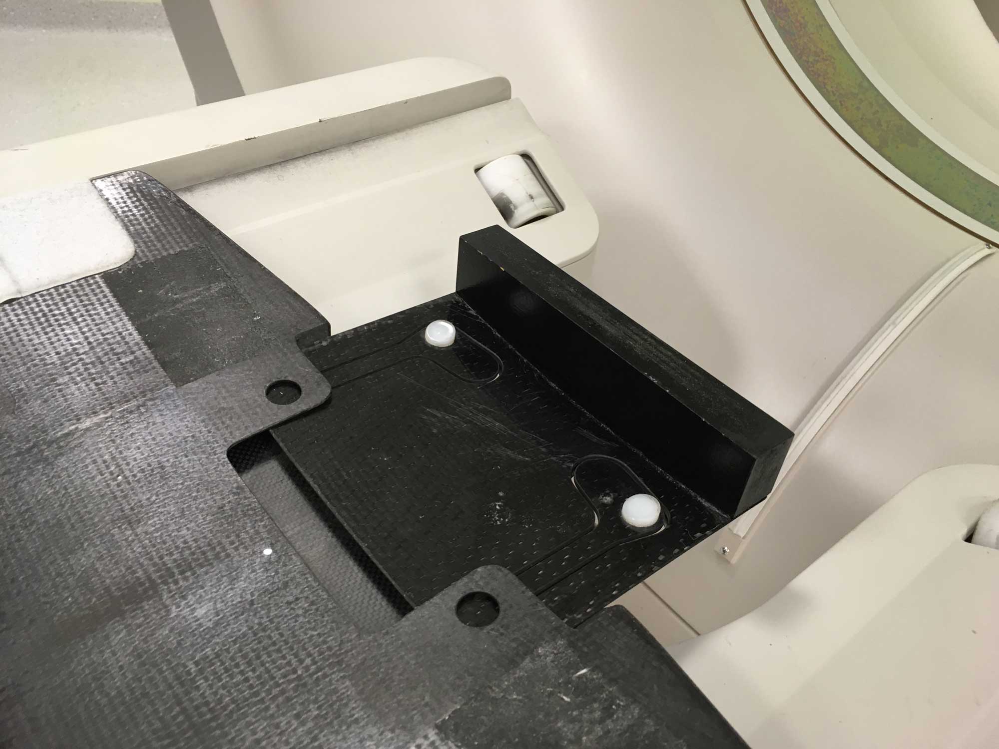
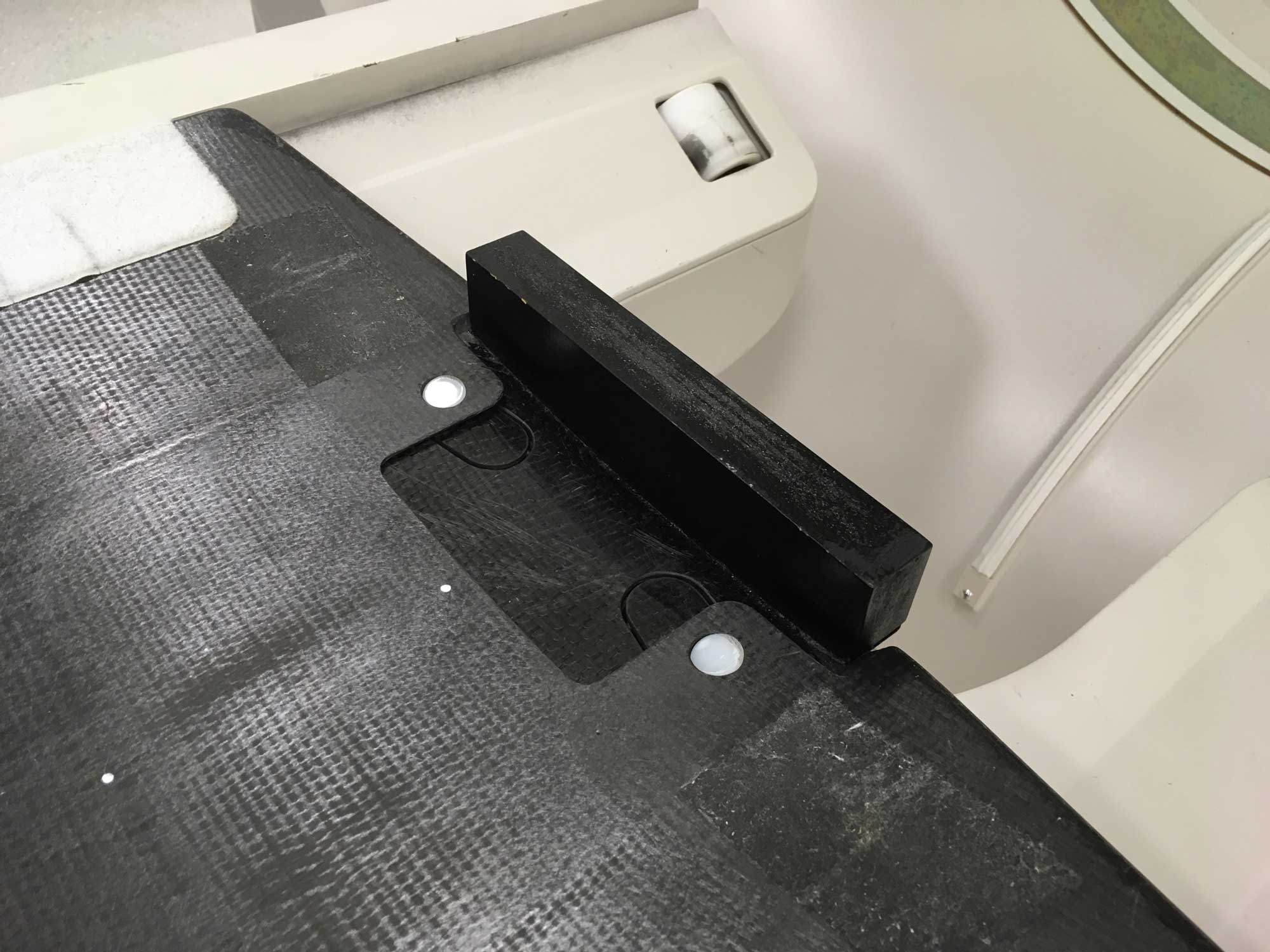
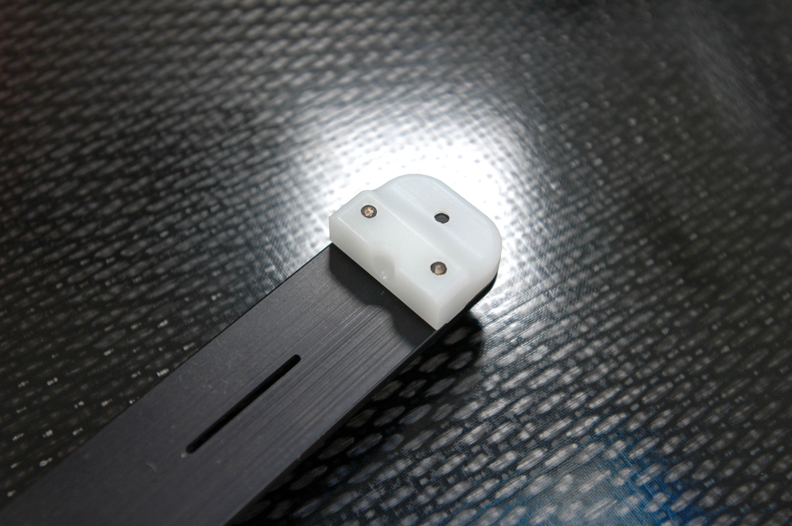
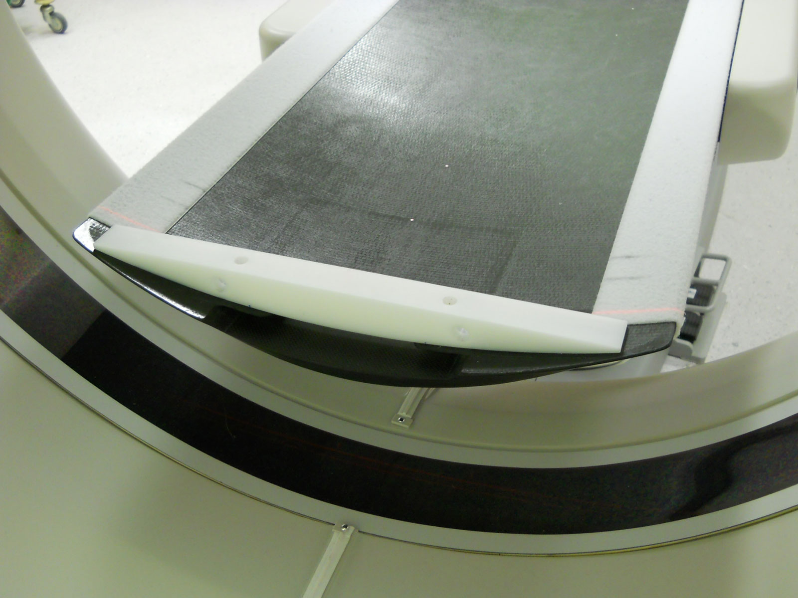
We also tested a modified setup, where the UCT was additionally supported at the cranial end by a block of plastic. The white block is part of the Varian RPM system where it is normally used to mount the camera on the couch. Since we use the 1.7 room-based RPM, the block was free for other uses. It fits into the curvature of the cradle (pic1, pic2, pic3, pic4).
Simulated Patient Load
To simulate patients of different weights, we used plastic containers filled with scrap metal. Four different total masses (40, 80, 140, 190 kg) were distributed on the overlay in the following patterns (each container has a mass of 10 kg):
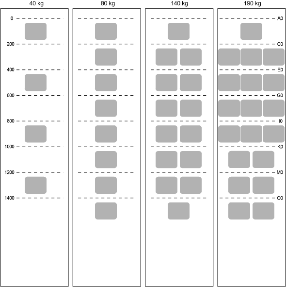
The maximum patient load of 190 kg was chosen for security reasons: The UCT itself has a mass of about 10 kg. The allowed maximum total load of the couch (patient + overlay) is 200 kg.
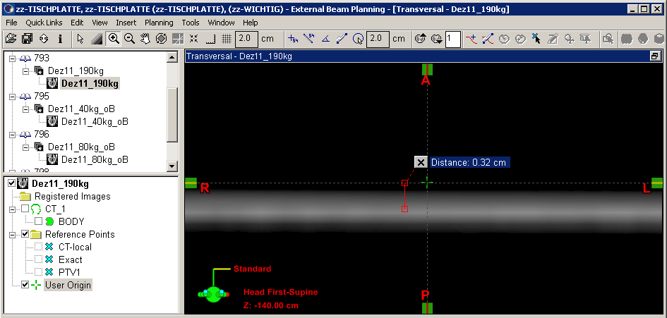
With each load from the above load pattern, eight single slices were acquired in the gaps between the containers (dashed lines) at the indexing positions A0, C0, E0, G0, I0, K0, M0, O0 for both setups (original and modified). With the couch zeroed at A0 this corresponds to the longitudinal positions 0, 200, 400, 600, 800, 1000, 1200 and 1400 mm. The vertical table position for all scans was 138 mm (center of vertical travel range).
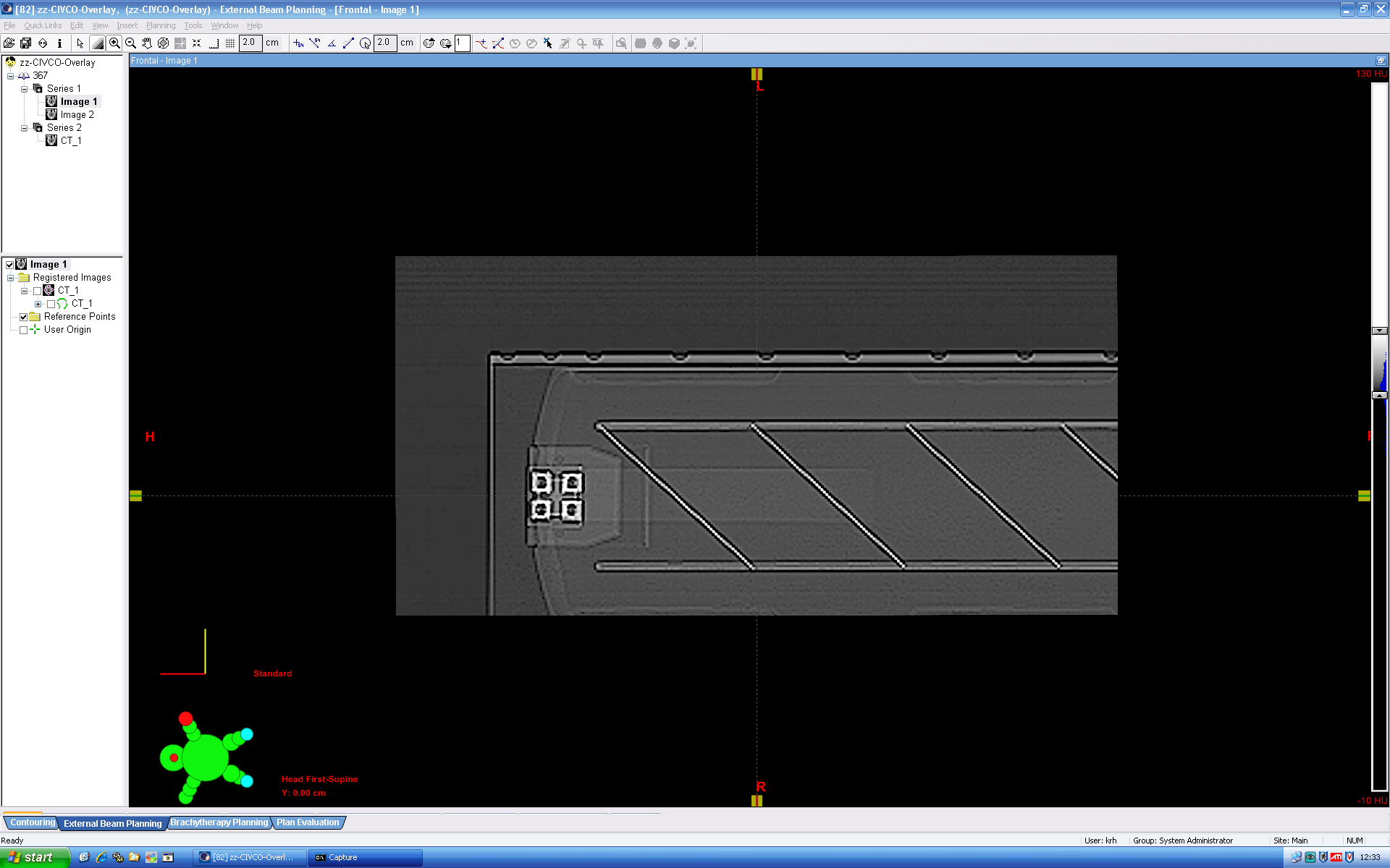
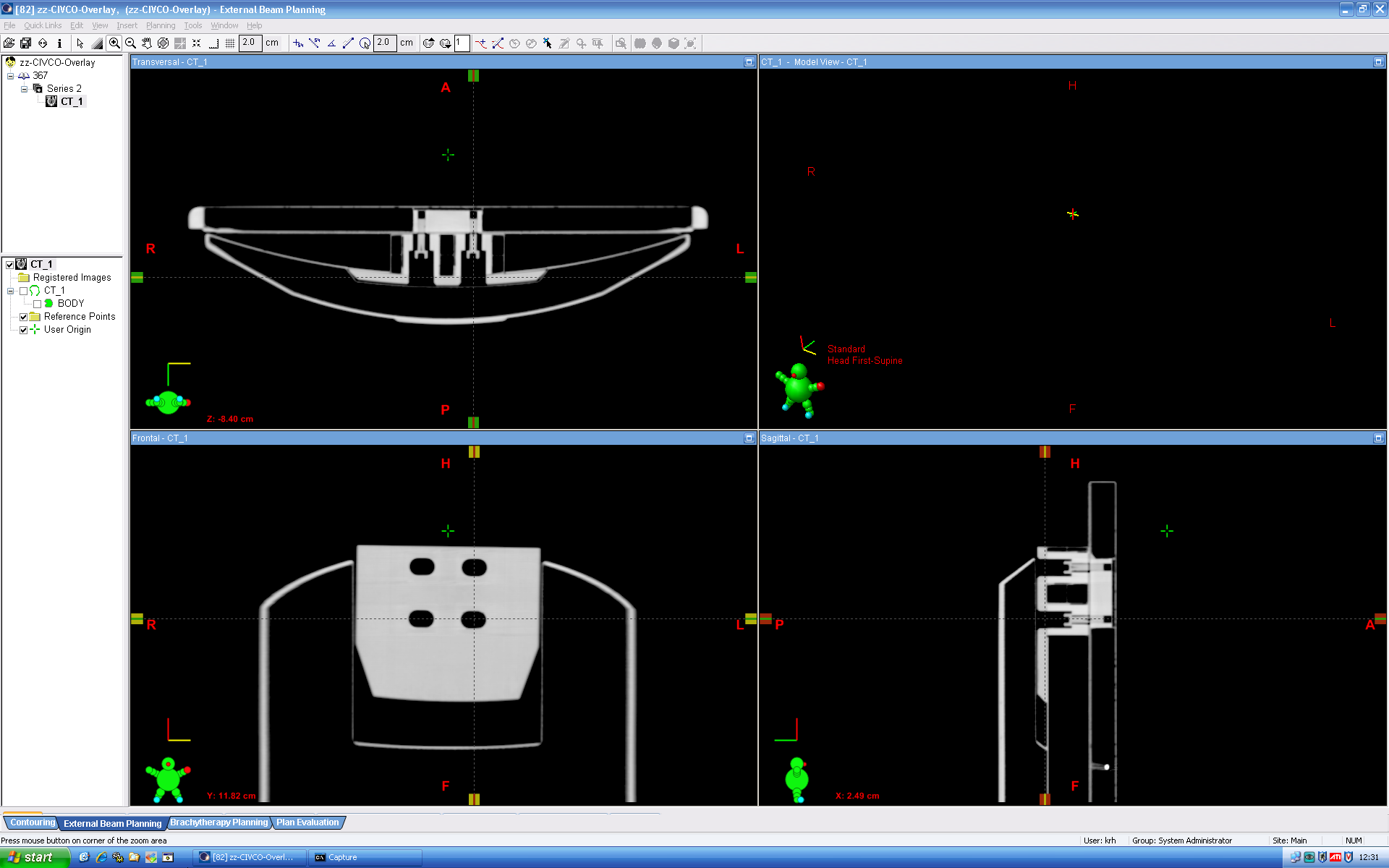
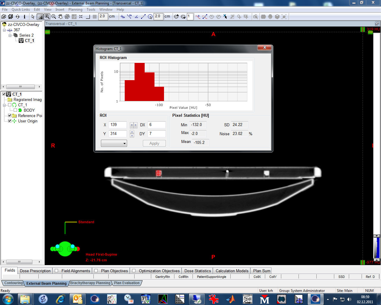
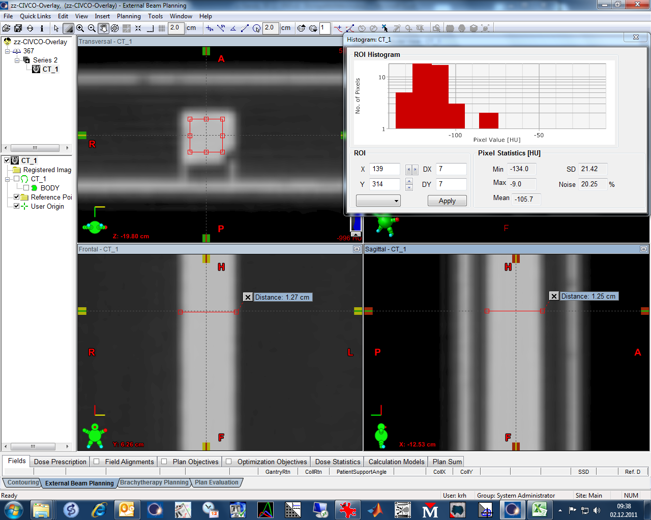
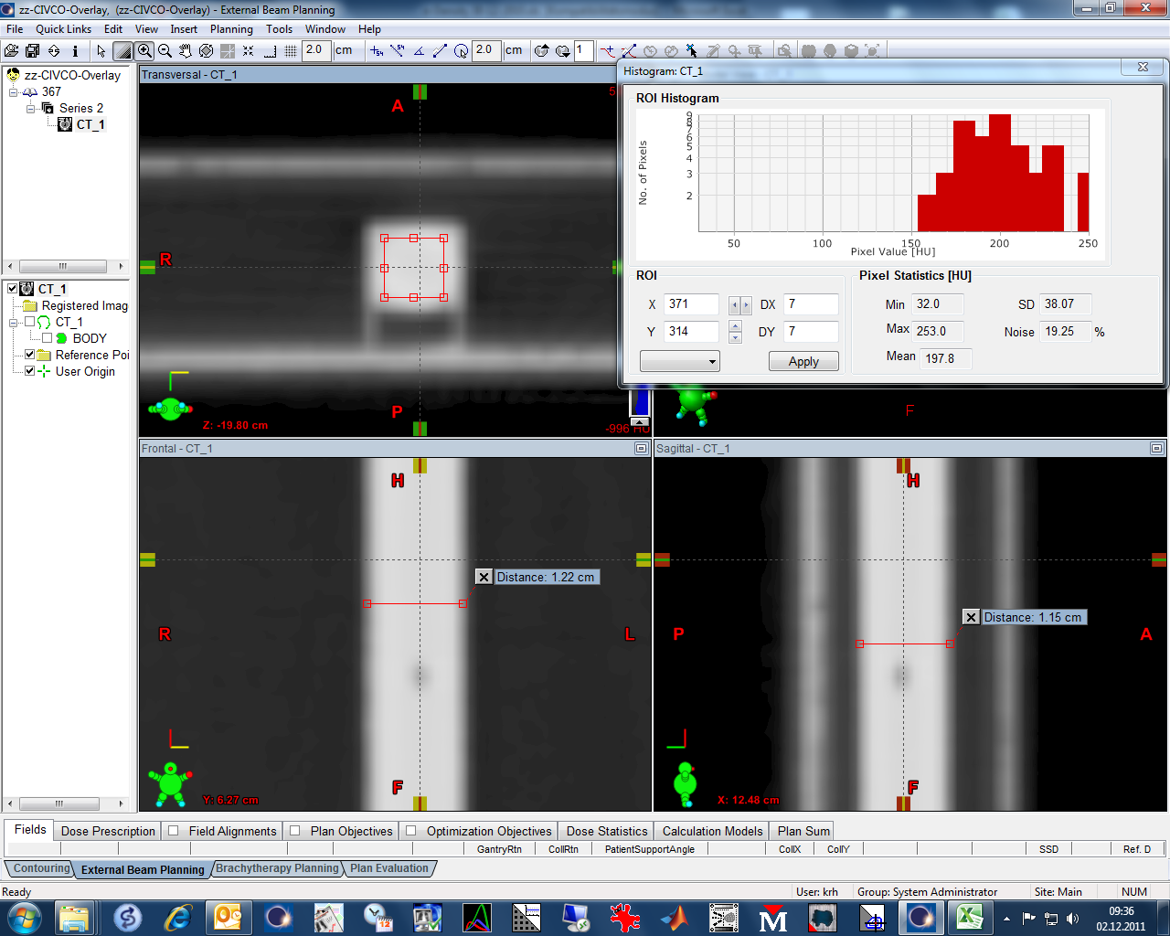
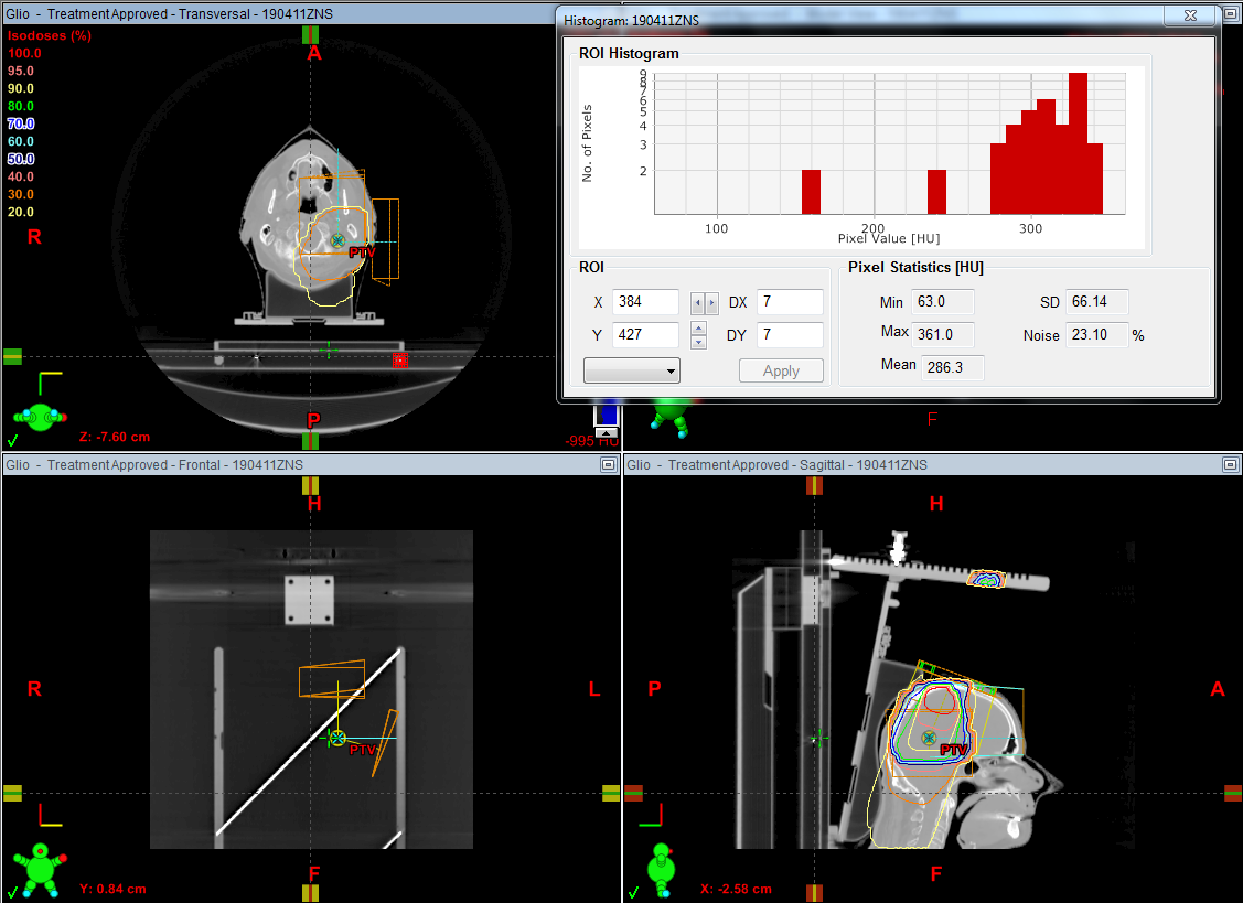
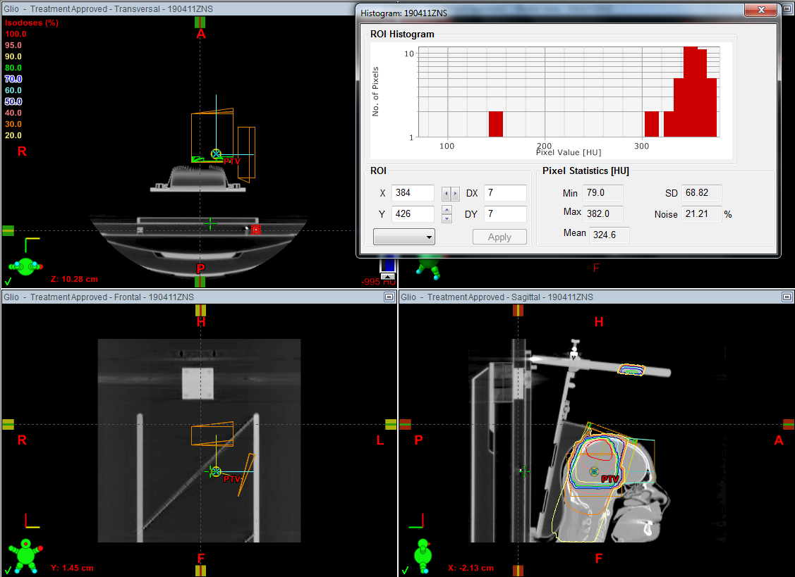
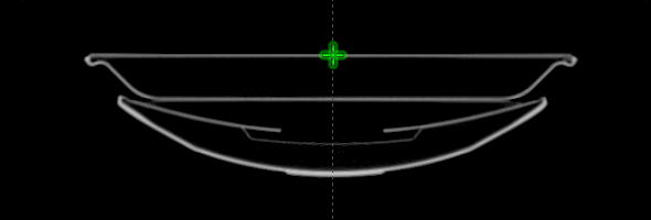
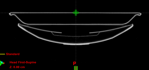
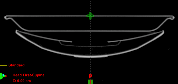
The 8 slices per scan were imported in Eclipse and a 3D image was generated. All measurements were performed in Eclipse. The user origin (green cross in the screenshot) was centered in the upper carbon surface of the UCT at A0.
When scrolling through the image stack, the user origin always remains visible. After zooming in, the vertical displacement can easily be measured with a precision of 0.1 mm and an estimated accuracy of 0.2 mm.
If the couch surface at some index position is higher than at A0, we say that the vertical displacement is positive. If the UCT surface sags down, it is negative.
In the modified setup, the placement of the white block is before A0. It is therefore not visible on routine patient scans.
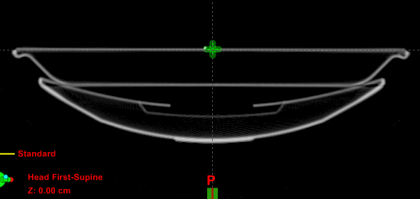
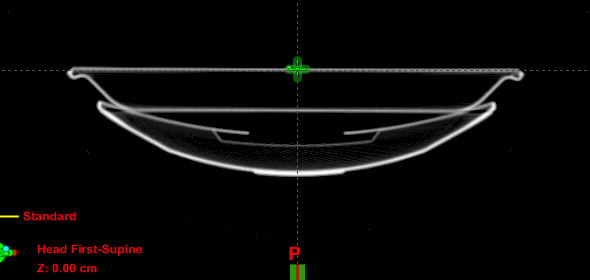
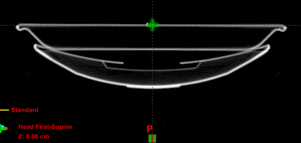
The curved bar which starts at 1269 mm (with the couch zeroed at the edge) is visible on all scans at 1200 mm (with the couch zeroed at A0). All other scans only show the UCT on top of the cradle.
Since the slices were scanned in between the containers, the patient load is never visible on the scans.
Toshiba engineers were always present, trying to optimize the geometry of the cradle after each modification of the UCT. We tried to optimize the couch system as a whole.
Results
Original Setup
As already described, in the original setup the UCT is only supported in the middle and at the end. With this unmodified setup, we measured the following vertical displacements. All values are in [mm]:
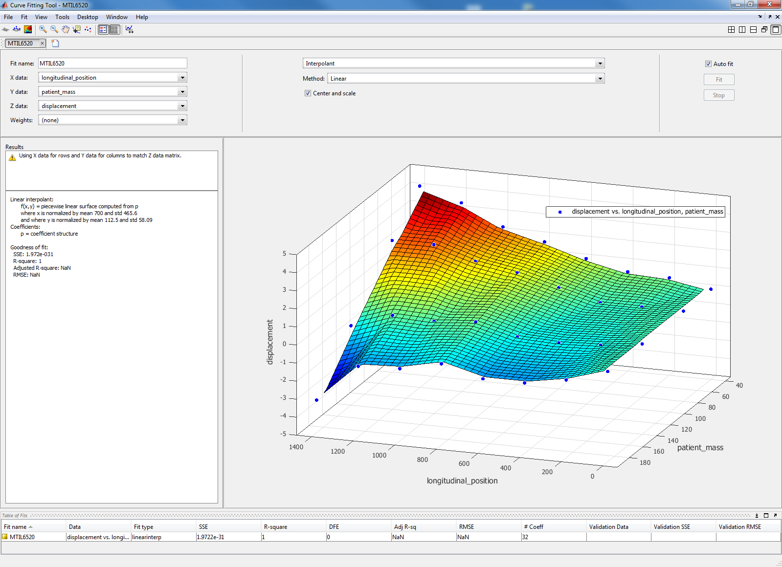
| Distance | Index | 40 kg | 80 kg | 140 kg | 190 kg |
|---|---|---|---|---|---|
| 0 | A0 | 0 | 0 | 0 | 0 |
| 200 | C0 | 1.8 | 1.4 | 1.1 | 0.7 |
| 400 | E0 | 3.2 | 2.9 | 2.0 | 1.7 |
| 600 | G0 | 4.9 | 4.4 | 3.5 | 3.1 |
| 800 | I0 | 6.6 | 6.3 | 5.4 | 4.6 |
| 1000 | K0 | 7.9 | 7.2 | 5.5 | 4.6 |
| 1200 | M0 | 9.1 | 8.3 | 6.7 | 4.7 |
| 1400 | O0 | 9.9 | 8.3 | 5.4 | 3.2 |
Relative to the height at A0, the surface always goes up. The biggest lift is seen with the smallest load (40 kg). When increasing load, the displacement slowly decreases, here for 80 kg:
Modified Setup (with Block)
The vertical displacements for the modified setup are shown in the following table:
| Distance | Index | 40 kg | 80 kg | 140 kg | 190 kg |
|---|---|---|---|---|---|
| 0 | A0 | 0 | 0 | 0 | 0 |
| 200 | C0 | 0.4 | 0 | -0.3 | -0.7 |
| 400 | E0 | 0.5 | 0 | -0.4 | -1.1 |
| 600 | G0 | 1.0 | 0.6 | -0.3 | -1.1 |
| 800 | I0 | 1.7 | 1.2 | 0.3 | -0.5 |
| 1000 | K0 | 2.3 | 1.6 | 0.1 | -1.0 |
| 1200 | M0 | 3.4 | 2.3 | 0.2 | -1.1 |
| 1400 | O0 | 4.1 | 2.3 | -0.6 | -3.2 |
This is the movement with the modified setup at 80 kg:
Discussion
It is clear from the data of the original setup, that its performance is totally unacceptable. When the couch moves into the Gantry, the UCT surface goes up in the scan plane quite dramatically (e.g., 6.3 mm at 800 mm and 80 kg). The UCT behaves like a wedge that is driven into the Gantry.
The UCT comes with a handful of yellow plastic washers which should allow some "fine tuning" of the setup. To get the UCT higher at the Gantry side, we introduced several washers under the curved bar, and rescanned. As the thickness of the plastic washers was too small to get significant improvement, we even added more metal washers (pic1, pic2). Note that if too many washers are used, the king pin won't slide into the base plate anymore, since the "angle of attack" is too high.
With the washers the performance only improved marginally. The scans in the results section were done without any washers.
The performance of the modified setup (with block) is significantly better. In the metal-free scan range (0 - 1200 mm), with the modified setup and a load of 140 kg, the UCT surface remains at the same height to within 0.5 mm. No washers were used in the modified setup.
With some fine-tuning (by changing the height of the block), the displacement could be optimized for a given target load. Our setup is currently optimal (showing the smallest vertical displacement) at 140 kg.
With interpolation, the expected vertical displacement can be determined for any intermediate mass or scan position:
Judging the displacements should take into account that the CT scans for RT planning are not performed over the full length of the overlay. The following drawing shows the UCT from the side (the Gantry is right) with the scan positions of typical treatments. Below the drawing is the curve of all vertical displacements, for both the original setup (without block) and the modified setup (with block):
Conclusion
While the UCT™ - One Piece is a perfect RT solution, the idea of designing the overlay like a springboard, not taking use of the CT's rigid cradle as a mechanical support, is rather strange. The cradle is "always there" - it is just 10 cm below the UCT surface - but in the original setup, it is simply not used as support. The overlay "floats" above the cradle.
The modified setup adds a custom block to support the UCT in the "classic" way (at the front end), without any drawbacks, and with very good results regarding vertical stability.
Final Setup
The modified setup was later replaced by a more elegant adapter, which uses the original carbon headrest (never used) that was delivered with the scanner. The base, which snaps into the cradle, has been cut off and a wooden block was added to it. Functionality of this final setup is the same as of the modified setup.