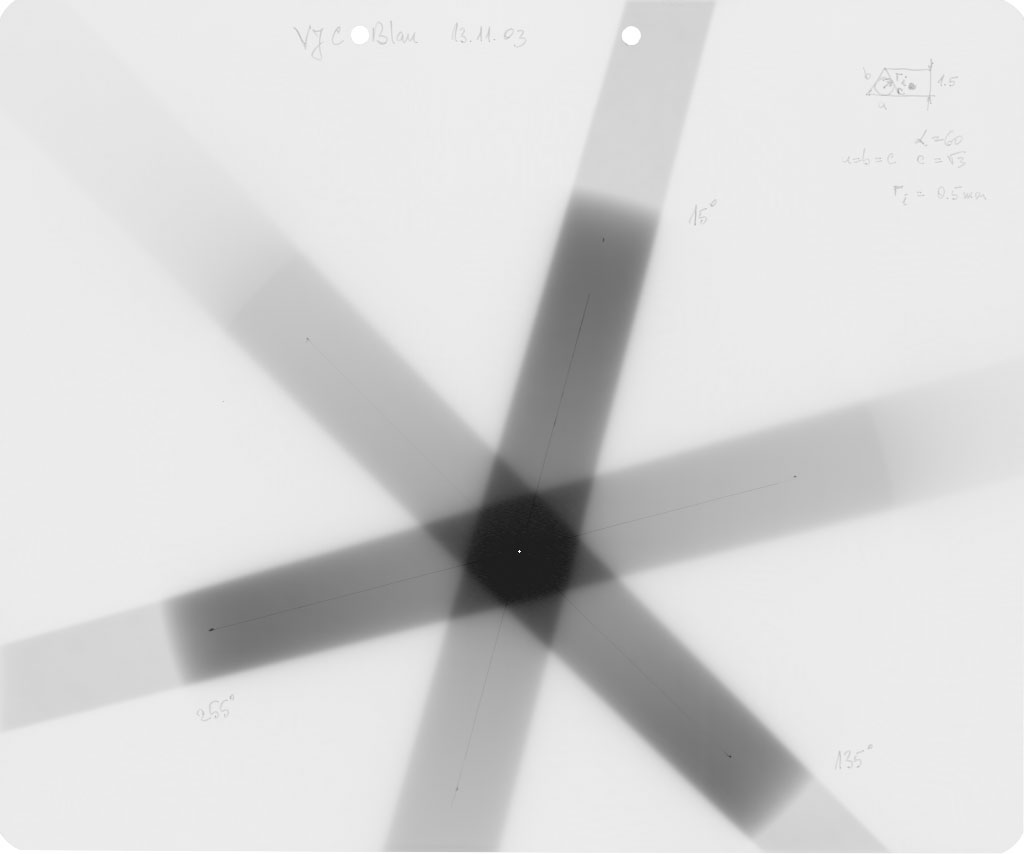
Fig.1: Star shot pattern on Kodak EDR2 film
The radiation isocenter (in contrast to the mechanical isocenter) is the point in space where radiation beams intersect when the Gantry is rotated during beam-on. This statement is a simplification: gravitation has an influence on the mechanical parts inside the treatment head and therefore on beam direction. The result is that the central radiation beams intersect geometrically in a small volume that looks more like a sphere or ellipsoid than a point. Usually the center-of-mass of this volume is called the radiation isocenter. It does not necessarily coincide with the mechanical isocenter, and it may even be different for different photon energies.
The radiation isocenter is an important point - usually the room lasers are adjusted to intersect at radiation isocenter. When radiation and mechanical isocenters practically coincide, the lasers may also be adjusted to the mechanical isocenter (which is usually much easier to accomplish).
The classical way to find the radiation isocenter is by exposing radiographic film (Fig.1) with a star shot pattern. The film is placed so that the beam enters through the edge of the film when it is irradiated from several directions (gantry angles) with a small field. In Fig.1, the gantry angles are 15°, 135° and 255°. The rotation axis of the gantry, running perpendicularly through the film, is marked with a needle (white point where beams intersect). The middle lines ("beams") of the three radiation stripes form a triangle when they intersect in the film center. The smallest circle which fits inside the triangle (all three beams have to intersect the circle or at least touch it) is usually called the radiation isocenter circle. Its size (diameter or radius) is often taken as a quality parameter of the linac.
|
Fig.1: Star shot pattern on Kodak EDR2 film |
Since film is planar, nothing can be said about the inplane- (gun-target-) direction. Two more films are needed so that the circle "becomes a sphere". Each film is exposed with two opposing rectangular films. The distance between the radiation centers of the opposing fields on each film complement the circle diameter found in the star shot. The largest value of the three films can be taken as the diameter of the radiation sphere in three dimensions (see e.g. ONORM S5290 or DIN 6847-5 for details).
The procedure described so far is not possible . It is not easy to set up the film on the treatment couch between slabs and mark the mechanical isocenter with the needle with the necessary high precision.
A more straightforward alternative to find the size and position of the radiation isocenter is the Winston-Lutz test. By using the aS500, the result has a much higher accuracy and involves no step where major inaccuracies can occur.
First, the linac jaws are set to a symmetric 4x4cm field. Special care has to be taken that the jaws open symmetrically (this also holds for the star shot!). If a jaw readout is slightly wrong (e.g., X1 opens to 2.05cm or 2.1cm but X2 opens to 2.0cm), this will have a direct impact on the size of the radiation isocenter ellipsoid in this direction. Simply check the symmetric field size using light field and ruler paper (this assumes that the crosshairs are aligned correctly and mark the central axis).
We place a 5mm steel marker (glued to a wooden stick) in isocenter according to the room lasers, which in our case point to the mechanical isocenter. Fig.2 shows the room setup.
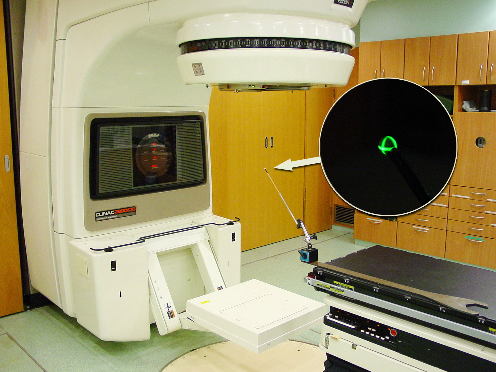 |
Fig.2: Setup for Winston-Lutz test. Gantry is currently at 0° |
The R-arm is positioned 83cm beyond isocenter for maximum resolution (0.43mm per pixel). Starting at Gantry 180° (IEC scale), port images (50MU, integrating mode) are acquired for each energy (6, 15MV) at increments of 30° with AM Maintenance (Fig.3).
 |
Fig.3: Acquiring an image in integrating mode with AM Maintenance |
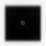
The gantry angles are: 180°, 210°, 240°, 270°, 300°, 0°, 30°, 60°, 90°, 120°, 150°, 180°. The 13 dicom images are saved for further processing. Fig.4 shows 12 of them.
 |
 |
 |
 |
180° |
210° |
240° |
270° |
 |
 |
 |
 |
300° |
330° |
0° |
30° |
 |
 |
 |
 |
60° |
90° |
120° |
150° |
Fig.4: Port images of a 4x4cm field (6MV) taken at different gantry angles |
|||
Here is an animation of the images, after the Canny filter has been used for edge detection (field, sphere and wooden stick are clearly visible. The rest is artefacts):
Fig.5 shows the coordinate systems: the room system (X, Y, Z) has the Y-axis pointing towards the gantry (=axis of gantry rotation). The film-oriented system (Mephysto software) will later give us the central axis (CAX) deviations inplane (ip) and crossplane (cp). The positive inplane direction is pointing away from the gantry. This system is rotating together with the films. The vertical blue ray in Fig.4 is the central axis of the field with gantry 0°. The first tilted image plane (30°) is also shown.
With respect to the image of the steel marker in the center (grey disk), in Fig.5 the radiation center of the 4x4cm field at 0° is shifted in +X and -Y direction. The positive Y-direction is also denoted as Target-Gun (T>G) direction, the positive X-direction as Left-Right (L>R). Z is pointing up.
 |
Fig.5: Coordinate systems used in Winston-Lutz test |
Processing steps: First, the images are converted to 8bit TIFF and magnified to 400%. Then they are opened with Mephysto like a scanned film. The origin of the Mephysto coordinate system is placed in the center of the steel marker (Fig.6) because this is the origin we want to refer to when determining the shift of the radiation field's center. Remember we placed the steel marker in the laser center.
 |
Fig.6: Setting the coordinate system and origin in Mephysto. Note that the direction Y in the Mephysto coordinate system is different from our room system (X,Y,Z) |
This is the only step where significant human errors may occur - the magnification of 400% reduces the inaccuracies. Then Inplane and crossplane profiles can be measured through the center (Fig.7).
 |
 |
| Fig.7: Measuring inplane and crossplane profiles (left), analyzing a profile for the CAX deviation (right). Note: all lengths are also magnified to 400% | |
The central axis deviation in the upper right corner of Fig.7 gives the shift of the center of the radiation field with respect to the steel marker in this plane.
The shifts can have different reasons. Here are some of them:
Fig.8 shows plots of the shift of the radiation center inplane and crossplane as a function of gantry angle. Each plane was evaluated twice by two persons, with similar results.
 |
Fig.8: Clinac Green, 6MV. The shift is not depending on the observer. |
 |
Fig.9: Clinac Green, 15MV. The shifts are identical to 6MV. This means that the radiation isocenters coincide. Again, there is practically no interobserver difference. |
How can we find out the diameter of the radiation isocenter sphere (ellipsoid)? First, we should plot the information of Figs.8 and 9 in a room-oriented fixed coordinate system, like (X,Y,Z). The image planes of Figs.8 and 9 are rotating around the gantry axis. To find the central axis points of the radiation field on each image in terms of room coordinates, one has to combine inplane and crossplane data and convert them to (X,Y,Z)-coordinates. The 13 points in space, which mark the central radiation axis of each beam, can be connected by lines, and the resulting polygon can be plotted in 3D (Fig.10).
 |
Fig.10: Clinac Green, 6MV. Cube size is 1.5mm, isocenter size is 1.2 - 1.3mm. |
The maximum distance between two arbitrary points on this polygon gives an upper limit of the radiation ellipsoid's diameter. The center of gravity of the polygon can be interpreted as the radiation isocenter position.
Clinac Green, Radiation Isocenter Coordinates and Isocenter Size |
||||
| Energy/Observer | X [mm] | Y [mm] | Z [mm] | Diameter [mm] |
| 6MV (HK) | +0.13 | -0.13 | -0.01 | 1.2 |
| 6MV (JR) | +0.12 | -0.15 | -0.02 | 1.3 |
| 15MV (HK, 1st run) | +0.13 | -0.12 | -0.01 | 1.1 |
| 15MV (HK, 2nd run) | +0.12 | -0.08 | -0.02 | 1.1 |
 |
Fig.11: Clinac Blue, 6MV. The pattern is somewhat different from Clinac Green, but the absolute magnitude is very similar. |
 |
Fig.12: Clinac Blue, 15MV. The 15MV crossplane curve (blue line) is slightly (0.2mm) shifted with respect to the 6MV crossplane curve. |
The overall diameter of the radiation isocenter sphere is about the same as for Clinac Green (Fig.13):
 |
Fig.13: Clinac Blue, 6MV radiation center polygon. Cube size is 1.5mm. Isocenter size is 1.0mm. |
Clinac Blue, Radiation Isocenter Coordinates and Isocenter Size |
||||
| Energy/Observer | X [mm] | Y [mm] | Z [mm] | Diameter [mm] |
| 6MV (HK) | +0.21 | -0.09 | +0.17 | 1.0 |
| 15MV (HK) | +0.22 | -0.02 | +0.17 | 0.7 |