MultiCheck 2.1
MultiCheck is a software for beam constancy checks with the 2D-ARRAY seven29.
Principle
The principle of constancy checks is to compare the actual measurement to a reference measurement. In the current context, this means that the linac beam is initially measured with the 2D-ARRAY under reference conditions (certain geometric setup, field size, energy, monitor units, temperature, pressure etc.). This is then declared as "reference measurement".
In the following periodic QA checks, the actual measurement is compared to the reference. Tolerances may be set. Exceeding a tolerance usually triggers a corrective action.
Setting up MultiCheck
The first step is to define the "Linac" for MultiCheck. Depending on the modalities (photons, electrons), field sizes (e.g., 10x10, 20x20, 26x26) and energies which should be checked periodically, a certain file structure consisting of empty folders has to be set up, which is easily done in MultiCheck directly (Fig.1), or in Windows (Fig.2).
Fig.1: Edit Linacs and Energies. Folders can only be created one after the other.
Fig.2: Setting up the structure of empty folders in Explorer saves time.
The advantage when doing this in Windows is that work can be saved by creating every folder only once, and copying it to the different locations. MultiCheck looks for files in the hierarchical order:
- Linac (Top level in "Data" folder, any name)
- Field Size (e.g. 20.0, meaning 20x20cm)
- Modality (Photons, Electrons, Protons, Neutrons, Cobalt)
- Energy (6.0 - no leading zero - 06.0 - allowed)
Linacs need not necessarily correspond to true machines. Linacs can also be called "Linac1-SSD80" or "Linac A, Gantry 90°" depending on the QA Task ...
Measuring the reference
In the following example, a 6MV 20x20cm photon field is prepared for constancy checks. We set up the ARRAY on the treatment couch "as is", that is without buildup or backscatter. SSD is 100cm, the ARRAY is centered to the linac's light field as good as possible.
After a warm-up time of 5 to 10 minutes, an offset measurement is performed (our duration: 60s).
The jaws of the linac are set to 20x20cm, and the reference field is measured (Fig.3):
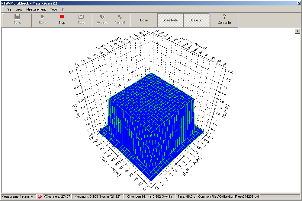
Fig.3: during reference scan 20x20cm, 6MV
After accepting the result, one gets back to the MultiCheck main screen (Fig.4):
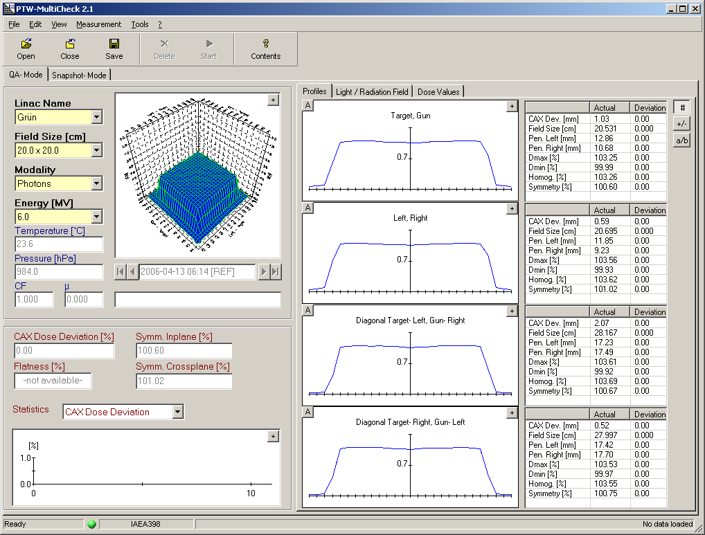
Fig.4: MultiCheck main screen with profiles display.
Photon reference measurements should also be done with jaw settings +1mm (Fig.5) and -1mm. This gives upper and lower limits for the periodic QA checks. In fact, the actual increment can be chosen by the user, but 1mm makes most sense: linac jaw readings usually have a precision of 1mm, and this is also the deviation one would tolerate in clinical routine.
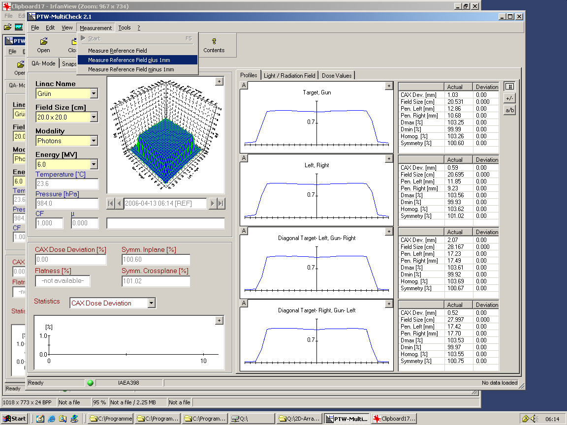
Fig.5: the +/-1mm reference field makes sense for photons, but is not mandatory. For electrons, only the reference field is measured if the electron field size is defined by a fixed applicator cutout.
Why it works
The concept of measuring reference field sizes of 20.2x20.2cm and 19.8x19.8cm is based on the fact that increasing or decreasing the field size by 1mm changes dose by ~10% in the edge chambers. The edge chamber's volume is only partly irradiated. If the fraction of the chamber's irradiated volume is changed slightly by increasing/decreasing the field size, the signal of this chamber changes significantly.
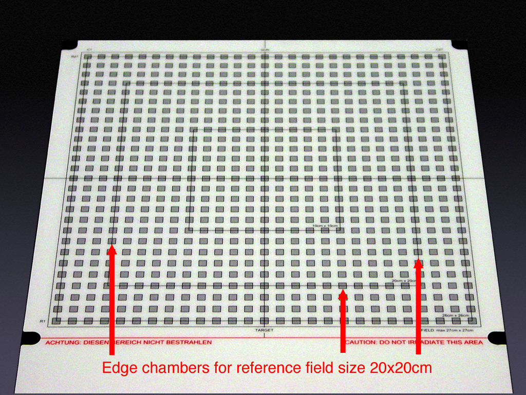
Fig.6: Any even field size may be chosen as reference. Here: 20x20cm
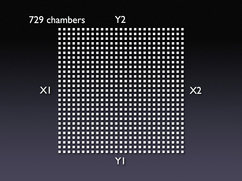
Fig.7: The ARRAY has 27x27 = 729 chambers
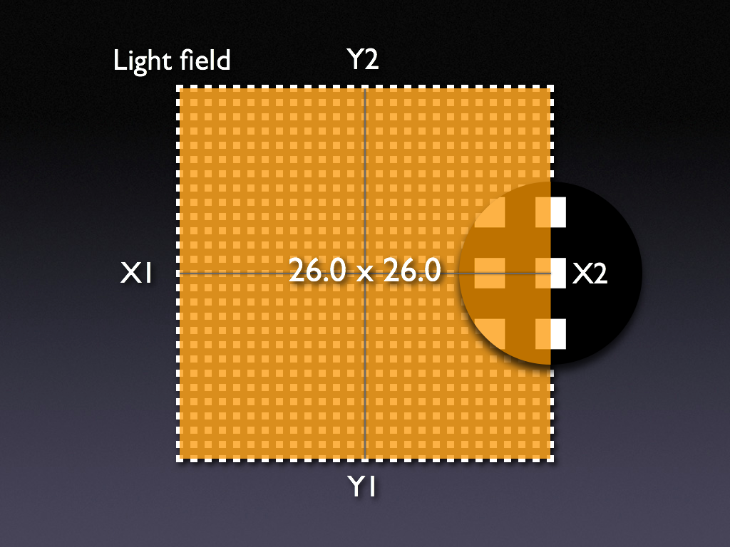
Fig.8: The largest reference field size therefore is 26x26cm. First step: align the ARRAY to the light field.
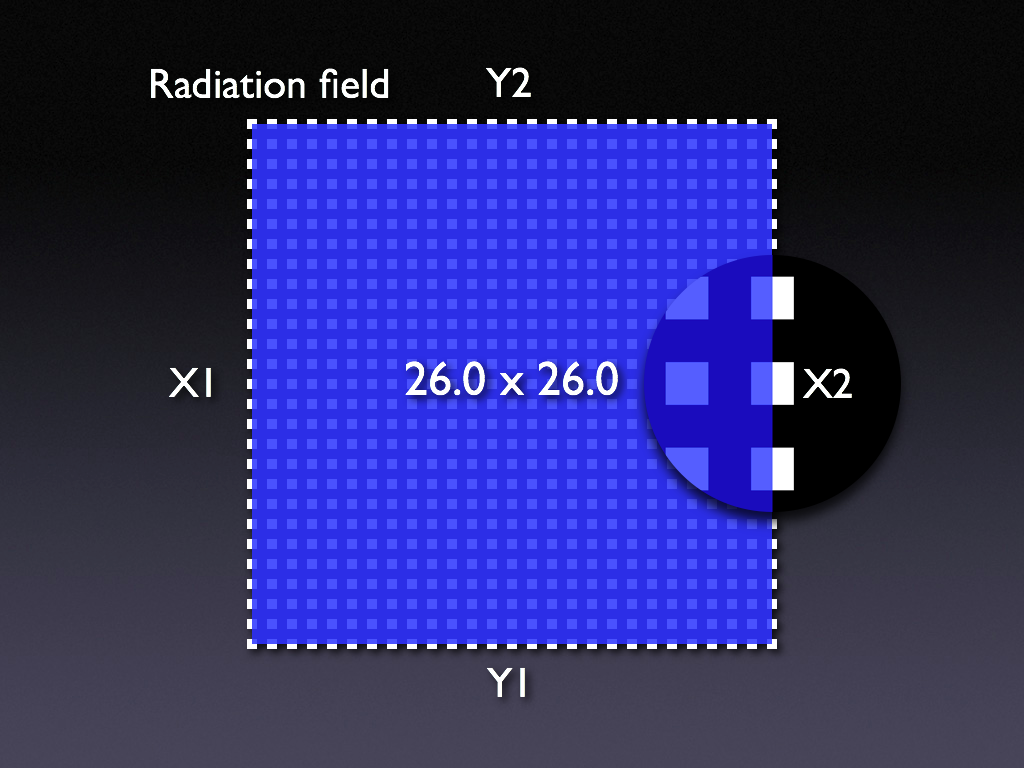
Fig.9: 2nd step: measure reference field size. We use 200MU, dose rate 300MU/min.
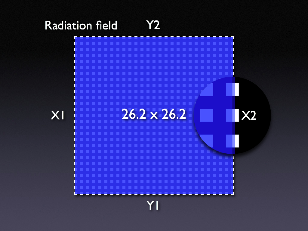
Fig.10: 3rd step: increase all jaws by 1mm, repeat measurement
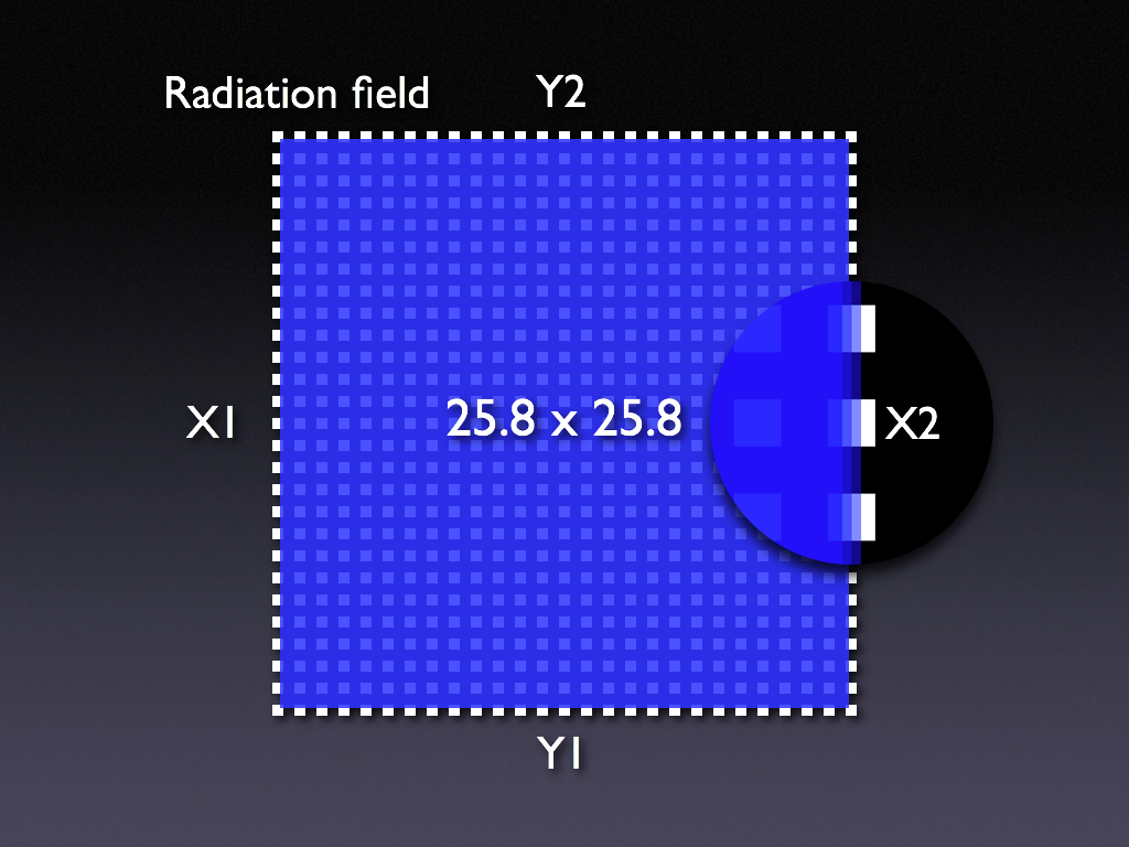
Fig.11: 4th step: once more for 25.8x25.8cm.
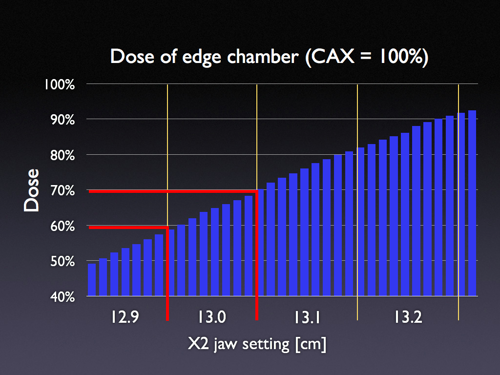
Fig.12: the jaws of the Varian linac have an internal precision of about 0.1mm (raw scale). This scale is visible to the user only in Service Mode. For this graph, jaws were positioned at precise raw scale positions and the dose of an edge chamber was measured. The X2 jaw setting on the abscissa is shown in clinical IEC scale mode (1mm precision).
One can see in Fig.12 that there are 8 to 9 different raw scale values which are converted to the same IEC scale value. Opening the jaw by 1mm increases dose by 10%. It can also be seen that the 50% dose value (dose is normalized to the central axis dose) is NOT found at the nominal jaw value of 13.0mm, but at a slightly lower jaw setting. This is because in the experiment the ARRAY was set up at SSD100cm, but the chambers are situated 5mm deeper (Figs.13-15):
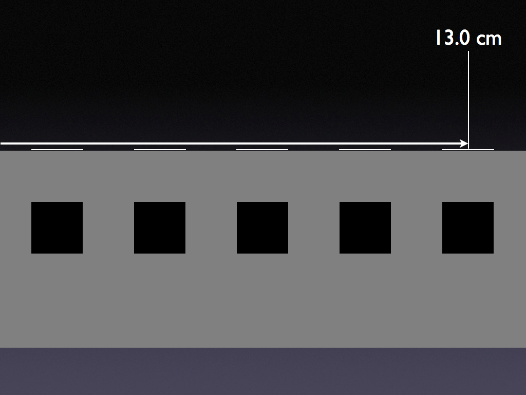
Fig.13: Transversal view of the 2D-ARRAY 729. The ionization chambers with a volume of 5x5x5mm are embedded in a depth of 5mm from the surface of the ARRAY. The white stripes on the surface are the chamber markers (see also Fig.6).
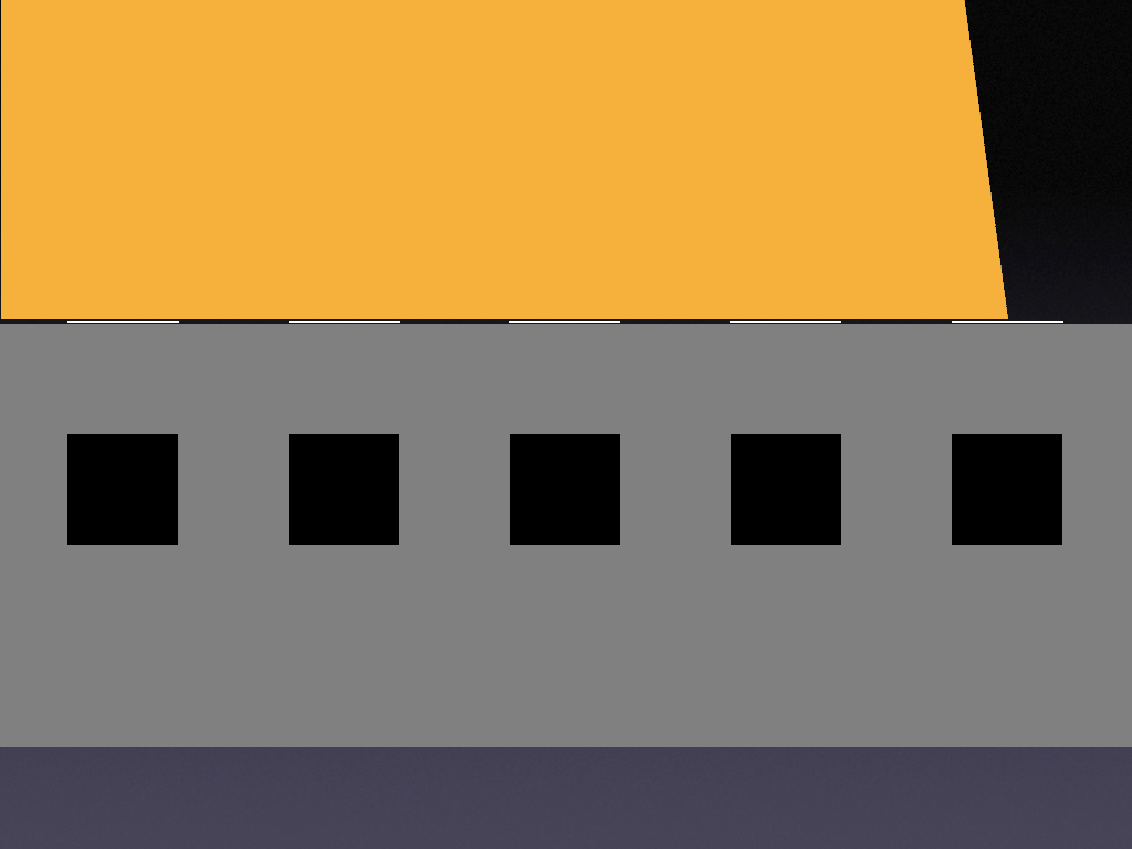
Fig.14: Here, the ARRAY is set up with a field size of 26x26cm. Therefore, the light field (orange) covers 50% of the chamber marker's area.
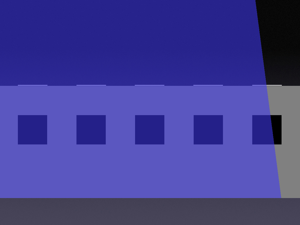
Fig.15: In contrast to the light field, the radiation field (blue) covers more than 50% of the edge chamber's volume, due to geometrical increase of field size. This is why the 50% dose of the edge chambers is not at the geometrical field size. Note however, that this has no practical consequence for the QA, if the +/-1mm approach is used.
Here are some more screenshots from MultiCheck:
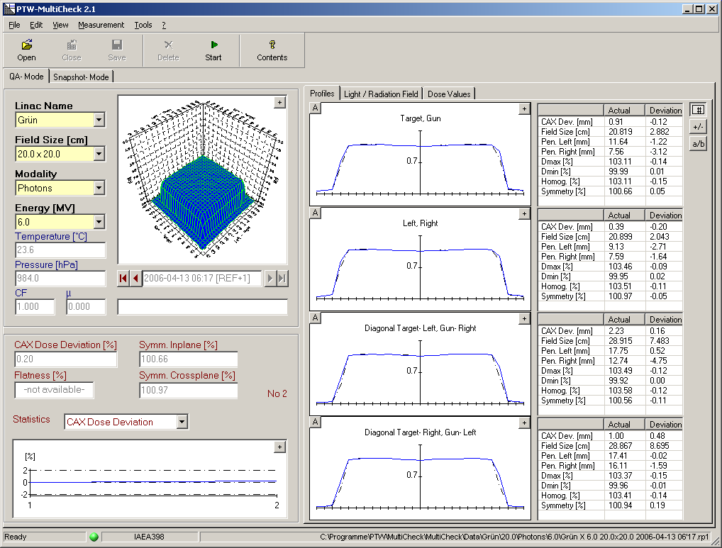
Fig.16: In the profiles tab, actual values of the scan are shown, together with deviations from the reference scan.
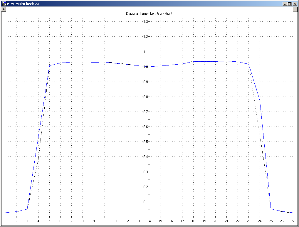
Fig.17: Clicking on the "+" icons in the upper right corners of the plots increases them to full size.
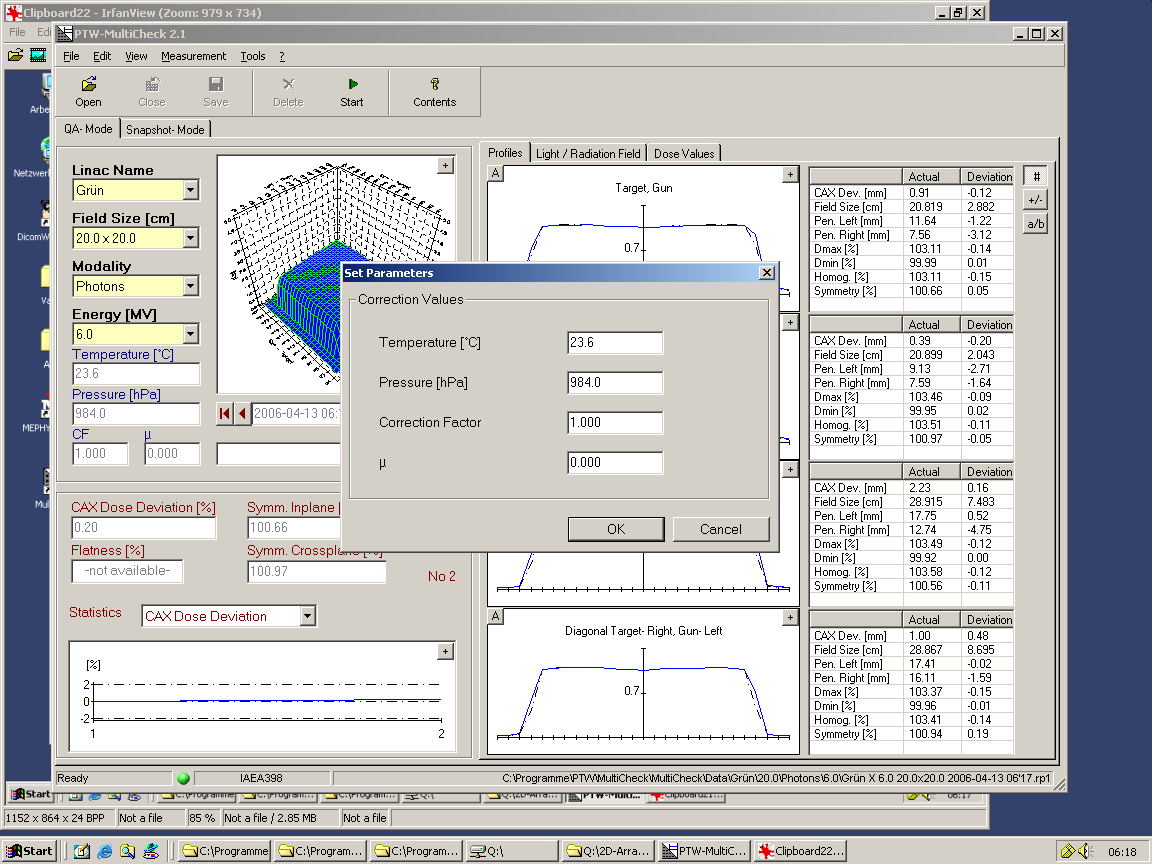
Fig.18: All measurements are corrected for air density, since ionization chambers are used. The user may enter an additional correction factor and (in case of wedges) an attenuation factor.
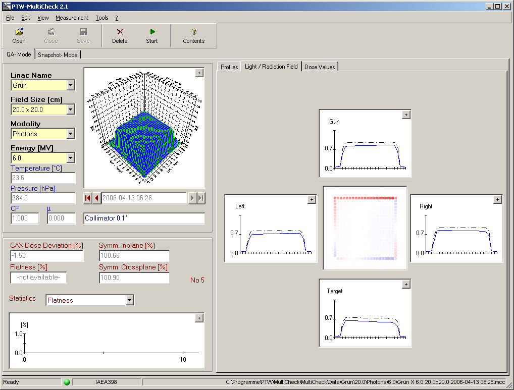
Fig.19: The Light/Radiation Field tab displays the edge profiles. Here, the collimator was rotated by 0.1°. The color coding shows overdose (red) and underdose (blue) when compared to the reference scan. The color scale sensitivity is set to full color at 0.1% deviation. This shows the sensitivity of the method. The 0.1° rotation is hardly visible on the light field.
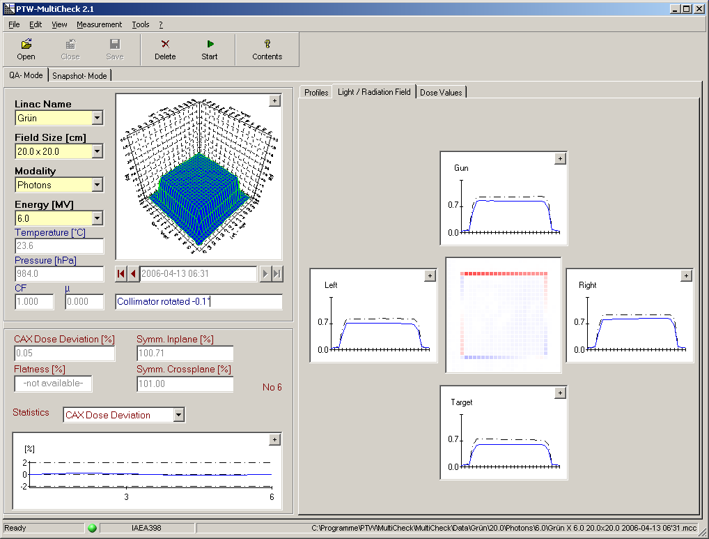
Fig.20: Here the collimator was rotated 0.1° in the other direction.
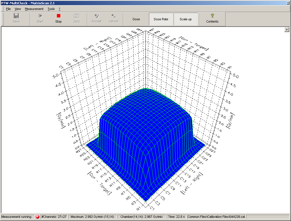
Fig.21: Electrons, 20x20cm, 4MeV (the energy which is hardest to measure). No problem with the 2D-ARRAY.
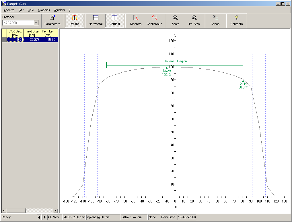
Fig.22: Clicking on the small "A" icons in the upper left corners of the profiles opens the beam analyze window. The profiles may be analyzed according to different protocols. Also user protocols can be defined.
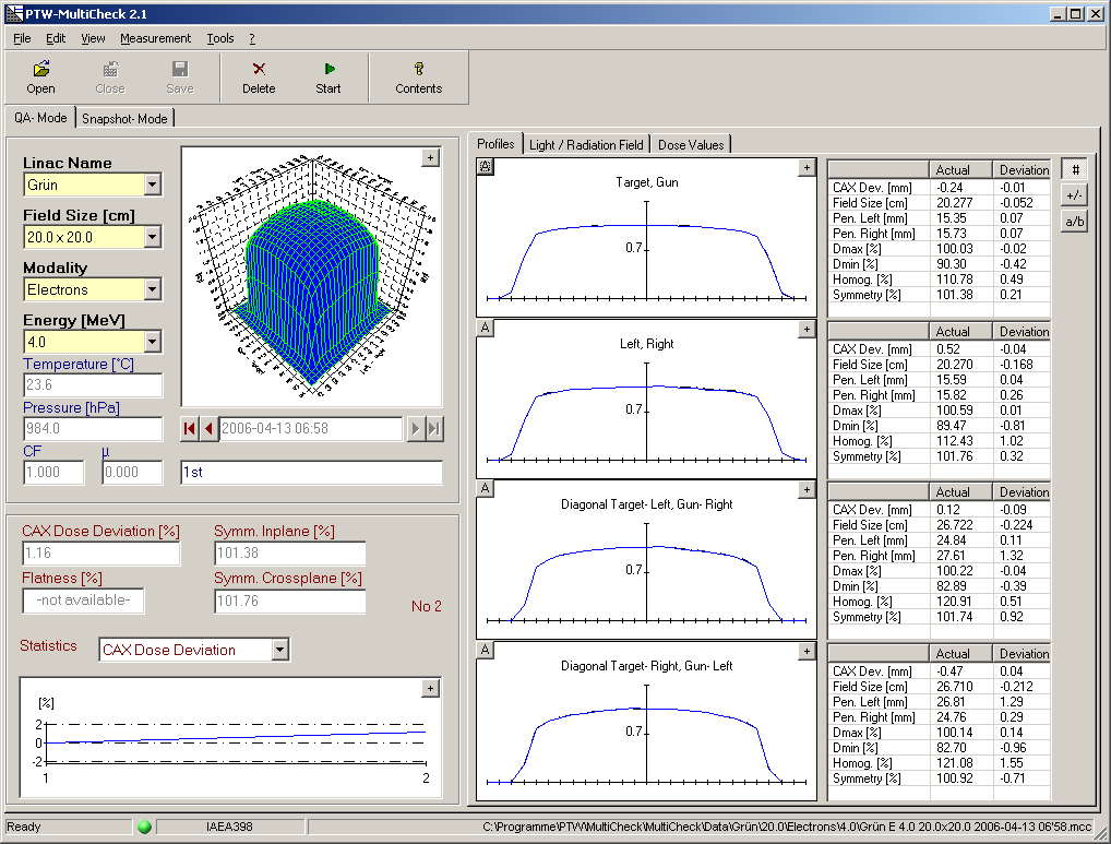
Fig.23: Another 4MeV scan. All photon and electron energies can be covered with MultiCheck QA.